Programmable relay switch using PIC MCU (revised version)
|
|
Programmable relays are key elements in numerous automation applications such as automatic street light control, watering and pump control, HVAC, home automation, power plants automation in industries, etc. This article describes a DIY programmable relay switch using PIC16F1847 (PIC16F628A can also be used) microcontroller. It is a revised version of my previous PIC-based relay timer project with added features and some improvements in the circuit design part. Like my previous version, it also allows you to set both ON and OFF times. The maximum time interval that you can set for ON and OFF operations is 99 hours and 59 minutes. The new version features cyclic option, which means you can choose to run it in a continuous loop of ON and OFF cycles. The timer can be programmed through 4 push switches. The programming menu, relay status (ON or OFF), and number of cycles completed are displayed on a 16×2 character LCD. The timing resolution of this relay timer is 1 minute. The timer also saves the previously-set ON/OFF times and the cyclic option in its internal EEPROM so that it can retain these values after any power supply interrupt. The firmware for this project is provided for both PIC16F1847 and PIC16F628A microcontrollers.
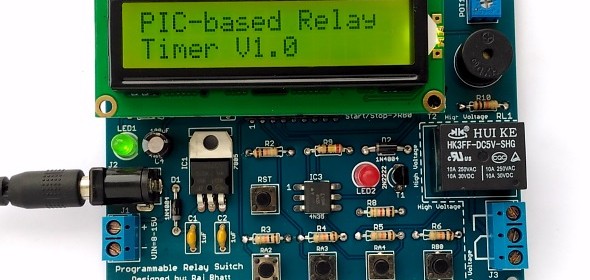
Programmable relay timer switch
Here are the summary of the features that this programmable relay switch has:
- On-board +5V voltage regulator (operates at 9-15V DC input)
- OFF and ON time setup for the relay operation
- Option for cyclic run (maximum 100 cycles, after which the timer stops automatically)
- Stores ON/OFF times and Cyclic option from previous setup into internal EEPROM
- ON/OFF timing range: 0 to 99 hours and 59 minutes with 1 min resolution
- Interactive user interface using 4 tact switches and a character LCD
- On-board buzzer alarm
You can buy the PCB for this project from Elecrow.
Circuit diagram
Let’s first talk about the hardware part of this relay timer project. It is not much different than the previous version except for a few improvements, such as an optical isolation between the microcontroller I/O pin and the relay control circuit, which will be discussed later.
Power supply: The entire circuit runs off a regulated 5V power supply derived from the LM7805 linear regulator chip (Figure 1). To minimize the heat dissipation in the voltage regulator, the recommended input DC voltage is 9V, which can be easily obtained from a DC wall adapter. The circuit board contains a 2-pin terminal block and a standard 2.1mm DC barrel jack to receive the unregulated input DC voltage. There is no power supply ON/OFF switch available on board this time.
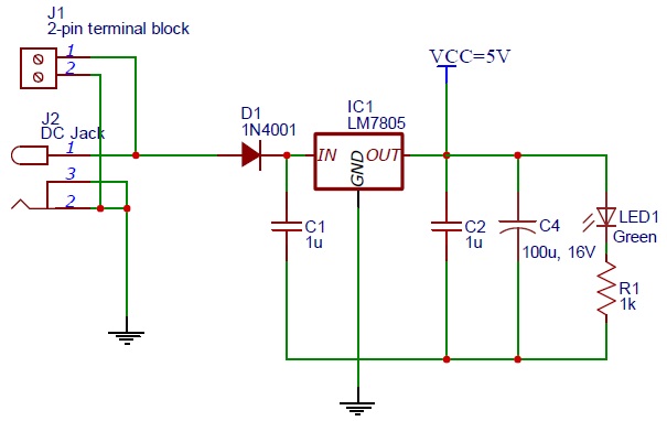
Figure 1: On-board +5V regulator circuit
Input and output
The I/O setup of this project is shown in Figure 2. There are five tact switches in this project: one for microcontroller reset, and four for user inputs. The four input switches are named as Menu/+, Select, Enter, and Start/Stop, and are pulled high under default conditions using pull-up resistors. Their functions will be described in the software section. The logic states of the 4 input switches are read by the PIC16F1847 (or PIC16F628A) microcontroller through ports RA2, RA3, RA4, and RB0. The output LCD is a standard HD44780-based display and is driven in 4-bit mode. The pin assignments for the LCD data and control signals are shown in Figure 2. The LCD backlight LED is turned on by tying its anode to +5V and cathode to GND through a 47 Ohm current limiting resistor in series.
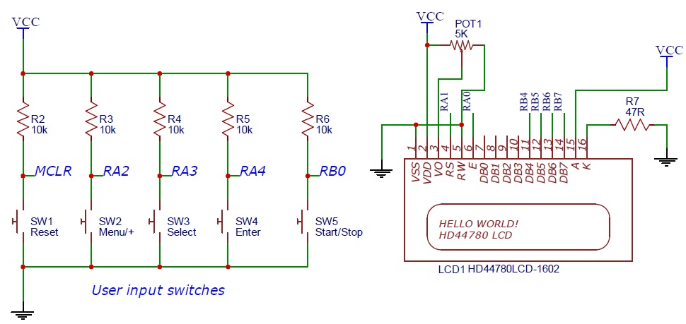
Figure 2: User inputs and LCD connections
A single NPN (2N2222) transistor-based switching circuit is implemented to drive the output relay. The switch is controlled through RB3 port of PIC16F1847. An optical isolation is provided between the microcontroller I/O pin and the relay driver using the 4N35 optocoupler. The project also includes a 5V DC buzzer (active) that beeps when the relay switch changes its state from ON to OFF and vice-versa. The relay and buzzer driver circuits are shown in Figure 3.
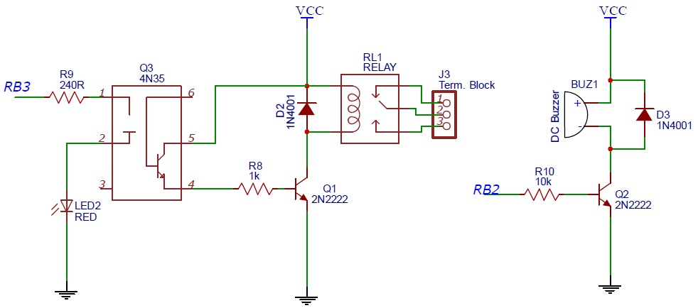
Figure 3: Relay and buzzer driver circuit
The PIC16F1847 microcontroller runs at 4.0 MHz using an external resonator. The I/O pins of the MCU, the resonator pins connections, and the in-circuit serial programmer (ICSP) header are shown in Figure 4. Because PIC16F628A and PIC16F1847 are pin-compatible, the circuit remains the same for both MCUs.
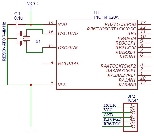
Figure 4: PIC16F628A/PIC16F1847 and external resonator connections
The PIC MCU pin assignments for the LCD, switches, relay and buzzer circuits are listed in the following table.
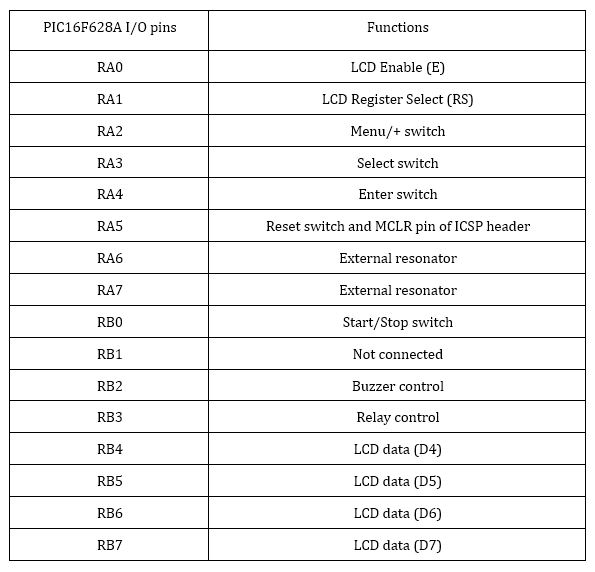
MCU pin assignments
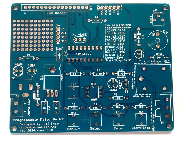
Printed circuit board
I designed a printed circuit board of the revised timer project which can be purchased from Elecrow. They ship it worldwide at reasonable shipping cost.
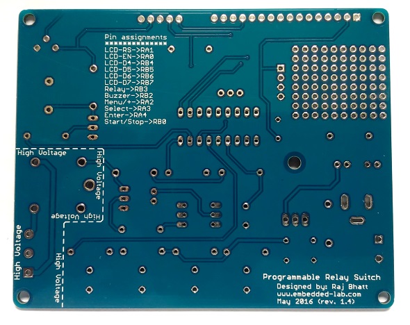
PCB: Bottom side
PCB: Top side
Note: The PCB also features access to the unused RB1 pin and a small prototyping area for adding extra functionality to this project. For example, an analog or 1-wire temperature sensor can be connected to this pin to build a thermostat application using the same board.
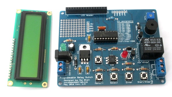
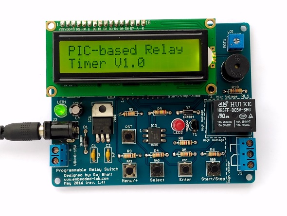
Assembled circuit board for PIC timer
Following is a complete list of components required to assemble the board.
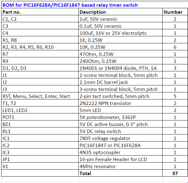
BOM for PIC timer project
The following excel sheet contains the same BOM along with the URLs for where you can buy these components.
Download PIC Relay Timer BOM Excel Sheet
Firmware
The programmable relay timer gets inputs from the 4 push buttons. Their functions are described as follows:
Menu/+ : This button allows you to navigate through various menu options such as ON time setup, OFF time setup, and Cyclic option setup. These options are displayed on the LCD. This button also serves as a digit incrementer (+) for setting ON/OFF time. The time is set in HH:MM format, which gives the minimum value of timing interval to be 1 min.
Select : This allows you to choose the currently displayed menu option on the LCD as well select between hour and minute digits. The selected digit is incremented by 1 when Menu/+ button is pressed.
Enter: When the appropriate hour and minutes are set, pressing the Enter button finalizes the time. The cyclic option is also set using this button.
Start/Stop: This push button is to start and stop the timer. After all user inputs are set, this button has to be pressed to start the timer. If the timer is already on, you can stop it at anytime during its operation by pressing this button.
Now let’s see how it works. Suppose, the relay switch is needed to be turned on after 15 minutes for 10 minutes. This means the OFF time is 15 minutes and ON time is 10 minutes. Once the timer is started after entering the above times, the device will be turned on after 15 minutes and remained on for 20 minutes. After that it will be turned off again. If the Cyclic option is selected to 1, the timer will run in a loop and after another 15 minutes of OFF time, the relay will be turned on for next 10 minutes, and so on until it completes 100 cycles. After completing the 100th cycle, the timer stops automatically. The number of cycles completed is displayed on the right side of the first row of the LCD display when the timer is ON.
The firmware for this project is developed using mikroC Pro for PIC compiler from mikroElektronika. The time keeping is achieved using the Timer 0 module built inside the PIC MCU. The Timer0 interrupt is enabled and run with 1:256 prescaler value to create a precise 500 ms (half-second) duration. The colon symbol between HH and MM digits blinks at 1 Hz. The half-second delay is looped 120 times to construct a minute-duration. Check out my tutorial on PIC Timer-0 module to learn how to create precise delays using timers. You can download the complete project files including the source code and compiled HEX files from the following links.
Output
Here’s a demo video showing the timer features in action.
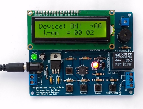
Timer is running and device is ON as indicated by red LED. 00 on top right indicates the first cycle has not completed yet. This number increment by 1 after the completion of each ON/OFF cycle (if Cyclic option is set to 1)
Click here to buy the PCB of this timer project.
References
All circuit diagrams used in this project are original and drawn by the author using the EasyEDA schematic editor. EasyEDA is a free online CAD tool for circuit layout, PCB design, and simulation.
|
|
I finally have my 2 Timers running but need them or at least one to count from 1 second. How can this be modified to basically count from 1 second and up (even if it is only up to 60 minutes)? Thank you.
R-B what tactile switches did you use? The BOM does not say other than 5mm lead spacing. It is hard to find 2 pin tactile switches with the 4 pin footprint far more common.
Thank you.
How can this be changed to a 1 second to say 99 minute timer? I often need a timer that runs for only a few seconds like often used to be used in photography dark rooms.
Thank you.
I do not see the LCD listed in the BOM. Which one did you use (2×16 ?)? Can a I2C enabled LCD be used instead?
Someone asked for the project files (in Proteus). Do you have a link to those?
Thank you.
The Elecrow link to the pc board is no longer valid. Do you have the board shared somewhere else like JLCPCB.com or PCBWay.com in their projects area?
The link is fixed.
This is a great project! I have it working perfectly now. Can the 100 cycle limitation be removed (made infinity)? I would like the loop to never stop and continue to cycle until my 9V battery runs out (or until the user presses the STOP button). Thanks!
Sir this project auto on and off repeated cycle programming
.yes or no sir tell mee.I want auto on off cycle repeat on and off program
PCB board price tell me Indian rupees sir pl
In this project which program kit uses .and send me kit name
Hello. i am very impressed with your project. i must say i built it and it worked very well. nothwithstanding, i would like to add the following.
1. i want to know how to make rb0 an automatic restart for the switch. for example main power went off, i dont want to press the start button before the device comes up. i want to be able to set rb0 to be gnd for 1 second, and remain up through out the simulation.
2. i am having issue with the relay. the relay triggers at the appopriate time, but it doesnt go off itself. nb: i used the hex file uploaded, im compiling through mickro c and i am uploading through pickit2
my ic is pic16f628a
thanks..
keep the good work
Hi my friend has installed this circuit but it is not understandable on the lsd screen, please have a working HEX file and if the characters are not already understood in the screenshots you can send email to gmail address alpy5282@gmail.com
Hi Victor, I have the same issue….. have you solved the point 1? if yes I would like to know the right way to do it…. thank you
Did you remembervthat this count down counter does minutes and hours. It does not do seconds which I woukd like it to do.
Sir ,
Can you please provide the nessasery change for timer in minutes and seconds.
Can you please upload the schematic of circuit to run on Proteus
Can u please explain the physical connection that you used to upload the firmware to the pic? Please respond sir I have a project due on Saturday!!
Sir please respond or take down this project because you only provide a method for creating the hardware and not dealing with the firmware. This is very misleading…..
Could you add a new link with a current PCB board as the links that are there at the moment do not work. I wish to purchase one for a school project.
Link is corrected. Thanks.
Thank you so much sir.
The link is broken again and gives the web 404 page not found error.
I just fixed the link. Thank you.
How can I upload programming to PIC16F628A/PIC16F1847. What is the cable configuration?
Hi, Built the timer and seems to work, but display is blank but lit up presume next process is to install program into PIC but not sure how has I never worked on these PIC chips before, I have the PIC16F628A chip, would be grateful for any help.
Regards John
Hi. I am Markuni from Jakarta, I would like to ask you a question: can this timer is modified to be Device ON at the first time instead of Device OFF since I don’t want to wait too long time after restart the timer when I set off time is 10 hours for example
Thank you for your help
Thank You,
I am waiting for such a useful project.
Will PCB be available in India by rupees
Thank you again for your effort.
Hello,
I achieved the installation “PIC-Based relay timer project” with a PIC 16F628A this last functions perfectly. I regret while the last programmed value is not memorized in the PIC.
The exam of the diagram of your new project seems identical for what is connections in the pic to your previous installation.
I programmed a 16F628A therefore with to put it PIC16F628A_Relay_Timer.hex while taking back the same configuration of fuses that for the RelayTimerWithLCD3.hex program that functions correctly.
At the time of the installation of the new PEAK on the former project the LCD presents a line of rectangles. The buttons seem to function correctly (displacement of a feature under the lign of rectangles, function active buzzer)
Is it about a bug of the Hex file or a bad configuration of the fuse?
Thank you for your answer and sorry for my French bad translation in English.
Thank you to erase my last commentary. I am distressed deeply to have criticized this installation that perfectly functions after correction of my mistake.
This last came of the inversion of the connections of writing and reading of the LCD.
These connections are reversed of an installation to the other.
Cordially
I agree with Lindsay Wilson.
It looks silly, Why to use optocopler on same Vcc? , Ground Planes near to Voltage CA ? , RB Port has “PullUp” instead of R3, R4, R5, R6, move your SWs to RB port,. It is a good idea to use the PWM to control the bright of back lit of the LCD and not only R7.
Are you using Fail-Safe Clock Monitor ? if not , use only RC clock intern instead cristal quarz. RC clock intern is enough for timer of hours.
To use a new pic as PIC16F1847 should redesign the circuit thus take advantage of a new chip.
I saw this over at Dangerous Prototypes (http://dangerousprototypes.com/blog/2016/06/30/programmable-relay-switch-using-pic-mcu-revised-version/) and there was a comment regarding the safety of the isolator and relay.
Number one, the copper ground plane appears to extend over the whole of the area marked “high voltage”. Considering the relay might be used to switch a 220V supply, this is extremely unsafe. The ground plane should be pulled back from the relay (on both sides) – the only copper present should be the traces from the output terminal block to the relay contacts.
Number two, the 4N35 optocoupler appears to do nothing. Both sides are run from the same Vcc supply, so it’s not providing any isolation.
It’s a really neat project, but I was a little bit scared by the lack of high-voltage isolation!
Hi Philip and Lindsay,
Thanks for your comments. The optocoupler in this circuit is used to provide an additional protection to PIC MCU I/O pin by providing a physical isolation from the relay circuit. I have seen this before when any high magnitude back EMF from relay damages the driver transistor, it is very likely to damage the MCU too. I agree that the current configuration of the optocoupler as used in this project does not provide a true isolation that it is meant for. That will require two different power supplies with separate grounds, which would be too cumbersome for this project. But it is a good idea to have that option available on board in case somebody would like to use it. I am going to add some header pins to allow users to configure the choice of power supply for the output side of the optocoupler.
I also agree the circuit ground plane needs more clearance near the AC supply pins.
The free wheeling diode is there to protect the transistor from being damaged. I created a PIC timer same as this (but without any optocouplers) since 2005 and it is still in operation. Also, there is another level of protection inside the PIC, the clamping diode on VSS and VCC. I agree with most of the comments, optocoupler is not needed.
Hello, sir. Can i add extra relay for this project and both relay can set a different timer
Great work.
May I ask why “an optical isolation is provided” and then you keep the same power supply for the relay? It seems really useless…