Author Archives: R-B

Overview of an Embedded System
Computer systems are everywhere. They fall into essentially two separate categories. The first and most obvious is that of the desktop computer. This is the machine that first comes in our mind when we talk about computers. Desktop computers are designed to be flexible and to meet a wide range of user needs. The end users can change the functionality of a desktop computer by simply changing the application program. One moment you may be using it as a word processor, the next you as an mp3 player or a game station.

The second type of computer is the embedded computer (or embedded system), a computer that is embedded into a bigger electronics system and repeatedly carrying out a particular function, often going completely unrecognized by the system’s user. If you ask somebody how many computers he has got in his home, he would probably count his desktop computer and his laptop. However, computers have always been embedded into all sorts of everyday items. In fact, he may have over 20 computers, hidden or embedded inside washing machines, TVs, digital cameras, cell phones, ovens, air conditioners, DVD players, etc. Unlike desktop computers, an embedded computer is normally dedicated to a specific task.

Definition: An embedded system is a computer system that is built to control one or a few dedicated functions, and is not designed to be programmed by the end user in the same way that a desktop computer is.

A user can make choices concerning the functionality but cannot change the system functionality by adding or replacing software. For example, a programmable digital thermostat has an embedded system that has a dedicated function of monitoring and controlling the surrounding temperature. You may have choices for setting the desired low and high temperatures but you cannot just change its functionality as a temperature controller. The software for an embedded system is often referred to as firmware, and is contained in the system’s non-volatile memory.

In most cases, an embedded system is used to replace an application-specific electronics in the consumer products. By doing so, most of the system’s functionality is encapsulated in the firmware that runs the system, and it is possible to change and upgrade the system by changing the firmware, while keeping the hardware same. This reduces the cost of production even lower because many different systems can share the same hardware base and the functionality is determined by the firmware loaded into them.

The another advantage of using an embedded computer to replace a dedicated electronics circuit is the protection of intellectual property. If your design is completely hardware based, it is easier to steal the design. All you need is to identify the circuit components and trace the tracks on the circuit board. With an embedded system, the hardware can be identified but the software, which really supplies the system’s functionality, can be hidden and more difficult to crack.

A short list of embedded systems

Cell phones, digital cameras, battery chargers, digital thermostats, traffic light controllers, digital watches, washers and dryers, ovens, fax machines, printers, televisions, DVD players, factory control, satellite phones, modems, network cards, pagers, portable video games, photocopiers, home security systems, mp3 players, ipod, cruise control, anti-lock brakes, air bag control, fuel injection control, flight attitude control, dish washers, answering machines, digital recorders, elevator control, surveillance systems, robots, voice recognizers, thumb readers, avionic systems, radar systems, navigation devices, camcorders, data loggers, oscilloscopes, signal generators, imaging systems, patient monitoring systems,  etc. They are everywhere!

Inside the embedded system

After learning that embedded systems are virtually found everywhere, lets explore the key components inside an embedded system.

Processor

At the heart of the embedded system is the central processing unit or processor. It is the hardware that executes the software and brings life to the embedded system. It also controls the activities of all the other circuits. There are varieties of processors available for embedded systems, and the main criteria for selection is  “Can it provide the processing power needed to perform the tasks within the system?” Besides, the system cost, power consumption, software development tools, and component availability are also important factors to be considered while selecting a processor for embedded system design.

Memory

The embedded system also has memory, often several different types in one system. The memory is used to store the software that the processor will run. It also provides storage for data such as program variables, intermediate results, status information and any other data generated throughout the operation. The memory is an important part of any embedded system because it may dictate how the software is designed, written, and developed.

Peripherals

An embedded system communicates with the outside world through peripherals. The main types of peripherals that are used include:

  • Digital inputs and outputs: These are simple external pins whose logic state can be controlled by the processor to either be a logic 1 or a logic 0. They can also be used as input pins so that the processor can receive binary inputs from the external world. They can be used individually or grouped together to create parallel ports.
  • Serial interfaces: These are interfaces that send or receive data using one or two pins in a serial mode. They are less complex to connect but are more complicated to program because the data may also be augmented with additional information as required by the data transfer protocol.
  • Analog to digital converters: While processors operate on the digital data, the surrounding world is analog in nature. Therefore, interfaces between the system and the external world requires analog to digital conversions and vice versa.
  • Displays: Displays are used by the processor to display the status information, error messages,  and output results. They could be simple LEDs, seven segment displays, or character LCD panels.
  • Keypads: Keypads are used by the end user to provide inputs to the embedded system. The inputs could be anything such as entering the password, changing functional settings, switching between menu items, etc.

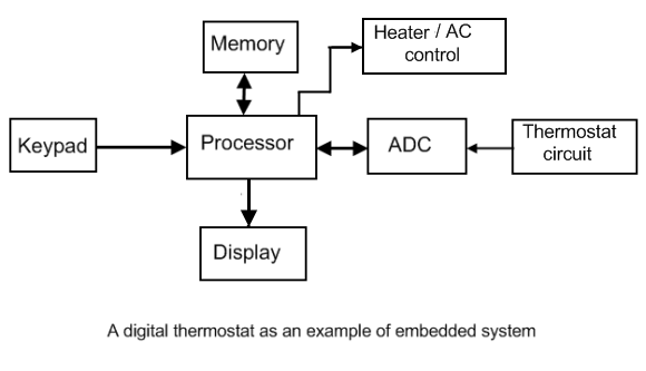
Lets now discuss about the embedded system inside a digital thermostat. The functional block diagram is shown below.

The surrounding temperature is sensed by the thermostat (a temperature sensor) and is converted to a proportional analog voltage. The processor cannot manipulate this signal directly, so it is converted to an equivalent digital number through a process called analog-to-digital conversion (ADC). The processor then compares this temperature reading with the high and low temperatures settings defined by the user, and turns the heater/AC on or off if required. The user uses Keypad to enter the temperature settings, which are saved into the memory. The processor displays the temperature settings and the current temperature on the LCD screen. The software to perform the entire function of monitoring and controlling the temperature is stored in the memory. The processor reads instructions from the memory and executes them.

References:

Embedded Systems Design by Steve Heath
Designing Embedded Hardware by John Catsoulis
Embedded System Design: A unified hardware/software introduction by Vahid and Givargis
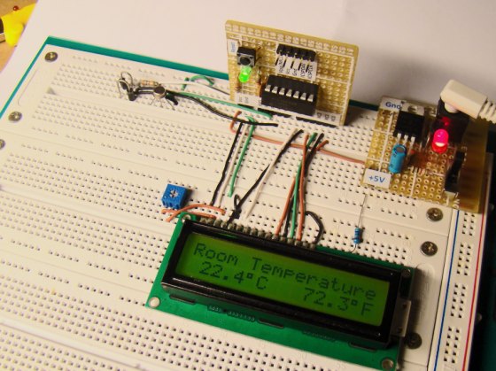
A Digital temperature meter using an LM35 temperature sensor

Introduction

A digital thermometer is a good choice of project for beginners who just stepped in to the world of microcontrollers because it provides an opportunity to learn using sensors to measure the real world signals that are analog in nature. This article describes a similar project based on a PIC16F688 microcontroller and an LM35 temperature sensor. LM35 is an analog sensor that converts the surrounding temperature to a proportional analog voltage. The output from the sensor is connected to one of the ADC channel inputs of the PIC16F688 microcontroller to derive the equivalent temperature value in digital format. The computed temperature is displayed in a 16×2 character LCD, in both °C and °F scales.

Theory

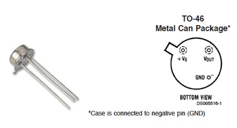
The LM35 series of temperature sensors are produced by National Semiconductor Corporation and are rated to operate over a -55 °C to 150°C temperature range. These sensors do not require any external calibration and the  output voltage is proportional to the temperature. The scale factor for temperature to voltage conversion is 10 mV per °C. The LM35 series sensors come in different packages. The one I used is in a hermatic TO-46 transistor package where the metal case is connected to the negative pin (Gnd).

Read more

Timers and counters

Introduction

Most microcontrollers are equipped with one or more precision timing systems that can be used to perform a variety of precision timer functions including generating events at specific times, determining the duration between two events, or counting events. Example applications that require generating events include generating an accurate 1 Hz signal in a digital watch, keeping a traffic light green for a specific duration, or communicating bits serially between devices at a specific rate, etc.

Theory of operation

The main component of such a timing system is a free running binary counter. The counter increments for each incoming timing pulse. The counter counts continuously from 0 to 2n-1, where n is the number of bits in the counter. Since it runs independently, it can count inputs or clock pulses concurrently while the microcontroller is executing the main program. If the input clock to the binary counter has a fixed known frequency, we can make an accurate measurement of time interval by counting the pulses from the clock. For example, if a particular clock’s frequency is 1 MHz (period 1 µs), and we have counted 3000 pulses on the clock signal, then the elapsed time is 3000 microseconds.

In microcontrollers, the input clock to the internal timing system is software selectable. The microcontroller’s own clock source (which is fixed) can be selected as the clock input to the free running counter module of the timing system. In such a case, the timing system is known to be working as a timer because it is driven by a fixed known frequency clock. However, the input clock to the timing system can also be provided through an external I/O pin of the microcontroller in which case it is known to be working as a counter, and will count the external pulses which may appear at random intervals. These pulses could be manual inputs from a push button, or more likely, would be produced by some other signal source, like a road sensor that generates a pulse every time a car is passed over it.

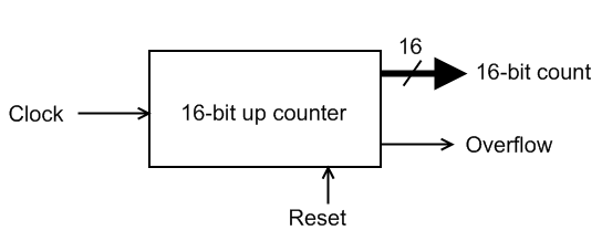
A functional structure of a simple timer module is shown below. This has a free running 16-bit up counter that increments its value on each clock pulse. Thus, the 16-bit output count represents the number of pulses arrived since the counter was last reset to zero. We can convert this value into time interval by knowing the frequency (or period) of the input clock signal.

Suppose, we want to measure the time elapsed between any two successive events. Lets assume that when the first event occurs, the timer is reset to zero, and when the second event occurs, the timer output is 25000. If we know that the input clock has period of 1 µs, then the time elapsed between the two events is 25000×1 µs = 25 milliseconds.

Since this timer’s counter can count from 0-65535 (216-1), this particular arrangement can measure time ranging from 0 to 65535 x 1 µs = 65.535 milliseconds, with a resolution of 1 µs. The maximum time interval a timer can measure is known as the timer’s range, whereas the resolution of a timer defines the minimum interval it can measure.

The timer module has an additional output, overflow flag, that indicates the counter reaches its maximum output, in which case the timer rolls over to 0. In microcontrollers, the built-in timers generate timer overflow interrupts when they roll over back to 0 after reaching their maximum counting range. We can count the number of times the timer overflows, and thus extend the range of time we can measure. In such a case,

elapsed time = (stop count – start count) + number of overflows x (2n-1),

where, n = 16 for a 16-bit counter.

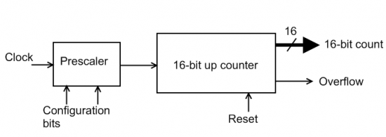
A more advanced timer has a prescaler (shown below). A prescaler is essentially a configurable clock-divider circuit. Depending on the selected configuration bits, the prescaler output could be the same as the input signal, or it may have half the frequency, one-fourth the frequency, one-eighth the frequency, etc. Thus, a prescaler can extend a timer’s range by reducing its resolution. For example, if we use a prescaler to our previous 16-bit timer to divide the clock frequency by 8, then the new range of the timer will be 65535 x 8 µs = 524.280 milliseconds. But the new resolution is reduced to 8 µs.

Timers in microcontrollers have additional configurable features such as enabling or stopping the counter, enabling or disabling interrupt generation when the counter overflows, selecting the clock edge for incrementing the counter, etc.

Lab 5: Analog-to-digital conversion (ADC)

Description

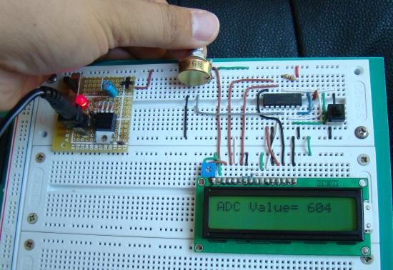
Analog-to-digital conversion (ADC) is necessary because, while embedded systems deal with digital values, their surroundings typically involve many analog signals such as, temperature, speed, pressure, the output of a microphone, etc. They all need to be converted into digital data before being processed by the microcontroller. Today, we will see how to read an external analog signal using a PIC16F688 microcontroller, and display the conversion output (a digital number) on a LCD. The input analog signal will be a varying voltage between 0-5V derived using a potentiometer.

Required Theory

The PIC16F688 microcontroller has a built-in 10-bit ADC with eight input channels. The eight channels are available at RA0, RA1, RA2, RA4, RC0, RC1, RC2, and RC3. They have alternate labels, AN0-AN7, for this function, and are multiplexed into a single Sample and Hold circuit. The output of the Sample and Hold is connected to the input of the A/D converter. The 10-bit conversion result is stored  into the ADC result registers ADRESH (A/D Result Higher byte) and ADRESL (A/D Result Lower byte). Each of these registers is 8-bit. The functionality of the A/D module is controlled by three registers: ANSEL, ADCON0, and ADCON1. The details of these control registers are discussed in ADC channels in PIC16F688.
Read more

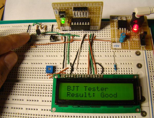
Microcontroller based Diode and Bipolar Junction Transistor (BJT) tester

Introduction

Most of the digital multimeters these days have built-in features for testing diodes and sometimes transistors. The purpose of this project is to demonstrate a simple way to construct a testing device for diodes and bipolar junction transitors (BJTs) using a microcontroller. The testing algorithm is based on a simple fact that a working PN junction conducts current in only one direction. A PIC16F688 microcontroller is used in this project that switches the bias voltage across the PN junctions of diode and transistors, and determines if a particular junction is normal, open or short.

Theory

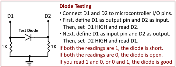
The logic behind testing a diode is straightforward. A diode is a PN junction that allows the conduction of current only in one direction. Therefore, a good diode will conduct current in only one direction. If it does in both the directions, it means the diode is short, and if it does in neither direction, it is open. The circuit implementation of this logic is shown below.

Read more

« Older Entries Recent Entries »