Author Archives: R-B

AM radio transmission using AVR
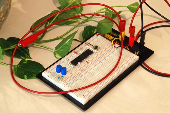
When you think about building a radio transmitter circuit, the first thing that comes in mind is it requires too many analog components. But wait a minute, this guy demonstrates an AM transmission using a microcontroller. The interesting part is it uses a plant as an antenna for transmission. This project is based on Atmega324 microcontroller, internally clocked at 8 MHz, and it generates a modulated AM signal using internal timers and counters. It uses TC1 timer/counter to generate a PWM signal of approximately 540 KHz. This is the carrier frequency. You know that before AM transmission, the high frequency carrier signal is modulated with a low frequency message signal. In this case, the carrier frequency is modulated by varying the duty cycle of the output PWM from 5% to 50% using TC0 timer/counter.

Read more

USB business card with a computer chip

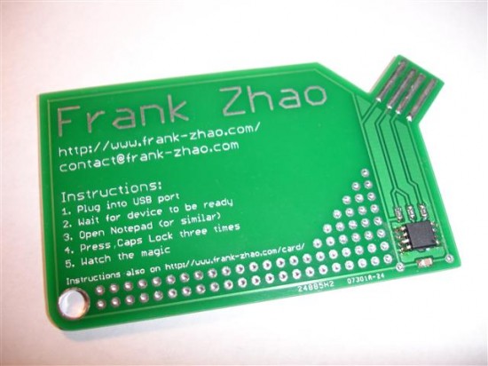
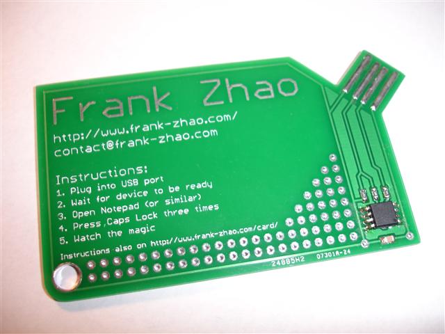
Have you ever seen a business card with a computer chip embedded on it? This one does. It has an ATtiny85 microcontroller chip that stores all your personal details. You plug it into an USB port of your computer, and find the details about the person opened into a text editor. The firmware uses V-USB (which is a software only implementation of USB) that allows the ATtiny85 microcontroller to act as an USB keyboard device, and type the stored info into the open text editor window.

Read more

A simple idea of making a digitally controlled variable power supply.

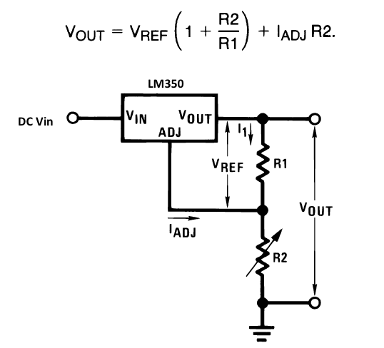
A variable power supply is a very useful tool for designing and testing electronics circuit. There are varieties of adjustable regulator IC’s available to generate a variable DC power supply. They normally use a two-resistor feedback network at the output to control the output voltage. If one of the resistor is replaced by a potentiometer, the output voltage can be easily adjusted as required. LM350 is one of such adjustable regulators that is capable of supplying in excess of 3A over a 1.2V to 33V output range, and is very easy to use. It requires only 2 external resistors to set the output voltage (shown below). Read the datasheet for more details on LM350. This project also uses an LM350 regulator with a microcontroller to control the output voltage.

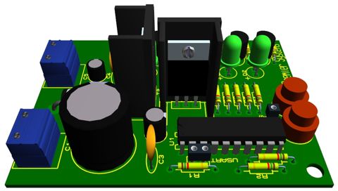
The role of the microcontroller in this project is to select an appropriate resistor for R2 from a resistor bank to control the output voltage. There are 5 resistors in the bank each of which is controlled by a seperate I/O pin from a microcontroller. The microcontroller turns a bipolar junction transistor ON and OFF to connect and disconnect a resistor across the R2 terminal points. The 5 individual resistors, seperately controlled by the microcontroller, can give rise to 32 different equivalent resistance values for R2, which means 32 different output voltages.


Read More

A simple parallel port programmer for ATMEL’s 20 pin microcontrollers

We hardly look for a programmer like this now a days because parallel ports are gone in modern desktop computers and laptops. However, if you still have got your old computer somewhere at a corner of your house, this programmer circuit might be useful to you. This programmer supports AT89C1051, AT89C2051, and AT89C4051 microcontrollers from ATMEL and uses an LPT (Line Print Terminal) port to communicate with the host computer. The programming software is free to download for non-commercial or personal use. You can download both DOS and Windows versions of the programming software.

Circuit diagram of the programmer (Source: www.epraktikum.iz.rs)


Read More

PIC-based Digital Voltmeter (DVM)

Introduction

This project will describe how to make a simple digital voltmeter (DVM) using a PIC16F688 microcontroller. The range of this DVM is 0-20V, but you can easily increase or decrease the range of input voltage as your requirements after you understand the voltage scaling method described in this project. The PIC micro reads the input voltage through one of the 8 analog channels and convert it to a 10-bit digital number using the internal ADC. Doing some math with ADC conversion (you will see later), this number can be converted to the actual measured voltage. The voltage is displayed in an HD44780-based character LCD.

Circuit Diagram and Description

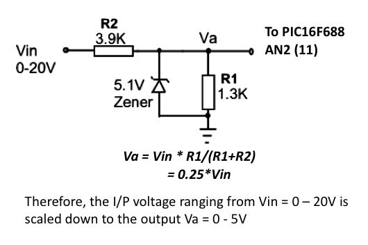
You cannot feed a 20V signal directly to a PIC microcontroller’s input channel. It is too higher than its operating voltage, and the microcontroller could be damaged. So, first we need a voltage scaler that will scale down the input voltage to the safe operating voltage range of PIC16F688. It can be achieved by a simple resistor divider network shown below.

Read more

« Older Entries Recent Entries »