Hookup guide for 16×32 RGB LED panel – Part 2
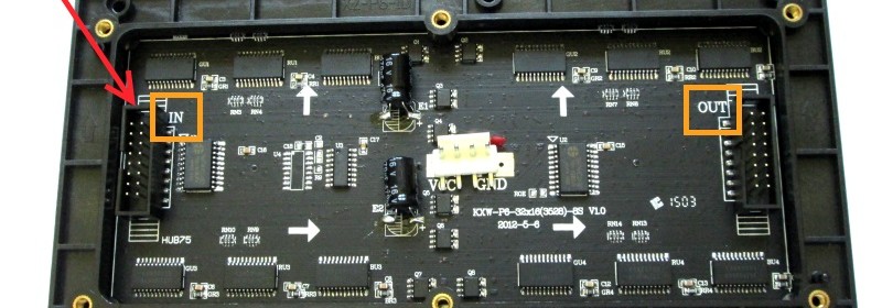
This is the second part of the 3-part article on how to hookup our 16×32 RGB LED panel kit to Arduino Uno. Click here to read the first part Step 3: Connecting the LED panel to the RGB connector shield The pin arrangement of the 2×8 IDC port (IN) on the back side of the RGB panel are shown below (image taken from Adafruit’s tutorial page). The 12 I/O pins of Arduino that are used to drive these signal lines are listed in the following table.
Read more


