Category Archives: LED display


Programmable LED dimmer using PIC16F18325

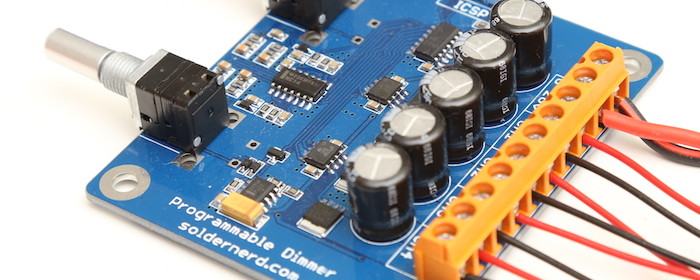
LUKAS FÄSSLER designed a versatile programmable LED dimmer using PIC16F18325 MCU to drive white and RGB LEDs. It operates at a wide range of power supply (6 to 26 volts) and utilizes MOSFET drivers with non-inverting outputs. The mosfet drivers are basically the same as before but now with non-inverting outputs: LM5111-1M. There are two of them for a total of 4 outputs compared to only 3 with the previous version. They now drive much (physically) smaller but no less capable mosfets which allowed me to significantly downsize the whole board to 75x65mm.  The NXP BUK9Y12-40E are rated at 40

Read more

RGB matrix displays time and environmental data

Temperature, humidity, and ambient pressure are the key parameters for environmental monitoring. With the advent of MEMS and integrated multi-sensor technologies, it’s been feasible to miniaturize environmental sensors and embed them into portable electronics. BME280 is one such fully integrated environmental unit from Bosch that combines sensors for pressure, humidity, and temperature in a tiny 8-pin metal-lid LGA package of size 2.5 x 2.5 x 0.93 mm³. This article describes how to read the environmental data from BME280 using Arduino and display the data on a 16×32 RGB matrix panel using the RGB driver shield. Things you will need Following items are used

Read more

16×32 RGB Matrix Panel Driver Shield Revision 1

Our RGB matrix panel driver shield for Arduino Uno has been slightly revised. The shield now also carries the DS1307 RTC chip on board along with a CR1220 coin cell battery holder on the back. It is applicable for driving popular 16×32 RGB matrix panels with HUB75 (8×2 IDC) connectors. Row and column driver circuits are already built on the back side of these matrix panel. The data and control signal pins for driving rows and columns are accessible through the HUB75 connector. It requires 12 digital I/O pins of Arduino Uno for full color control. The revised version also has a slide

Read more

Hookup guide for 16×32 RGB LED panel – Part 3

In this third part of the 16×32 RGB LED panel hookup guide, we will run some demo sketches with Arduino Uno to display basic text and animation on the 16×32 RGB LED matrix. These demo programs use Adafruit’s RGBMatrixPanel Library are found inside its Example folder. The wiring between the RGB panel and Arduino Uno is discussed in detail in the previous parts of this 3-part tutorial. Click here to read Part 1 of this tutorial Click here to read Part 2 of this tutorial Click here to buy this kit from our US Tindie store Get this RGB panel kit

Read more

Hookup guide for 16×32 RGB LED panel – Part 2

This is the second part of the 3-part article on how to hookup our 16×32 RGB LED panel kit to Arduino Uno. Click here to read the first part Step 3: Connecting the LED panel to the RGB connector shield The pin arrangement of the 2×8 IDC port (IN) on the back side of the RGB panel are shown below (image taken from Adafruit’s tutorial page). The 12 I/O pins of Arduino that are used to drive these signal lines are listed in the following table.

Read more
« Older Entries