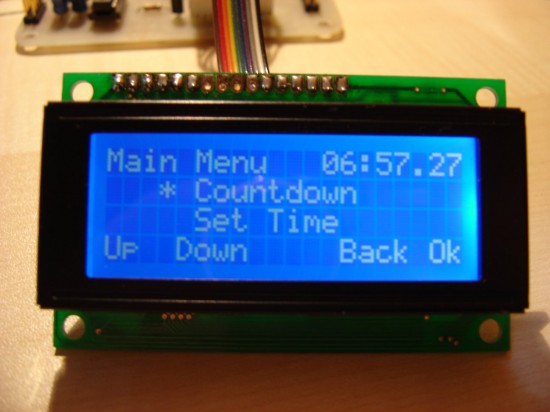
Digital alarm clock using PIC

|
|
This project describes a digital clock with alarm function. It uses a PIC16F877 microcontroller to generate an accurate 1 sec delay with Timer0 using Roman’s zero error method. The time is displayed in large size font on a 4×20 character LCD that uses HD44780 display driver. You can synchronize the time with your computer time through a serial port.
The required power is provided through a 9 V wall adapter which is used to obtain a regulated +5 V power supply using a LM7805 IC. The microcontroller runs with a 20 MHz external clock. The backlight of LCD is driven by a PWM output from the microcontroller so that the back light intensity can be varied. The full software written in JAL is available to download.
|
|

please can you mail me the schematic and .c file.
hafizy30@gmail.com
please can you mail me the schematic and .c file.
degiftedj@gmail.com
Did he send it to you??
can you send me the schematic and source code in .hex…please><
i got problem with this schematic because its not clearly because some of component not show the value of component.if not you sent me the complete clock with alarm function..if its work i will paid to you…
this is website that i try to simulate..but its not working..can you help me..www.dekimono.com