Easy Pulse mikro – A mikroBus compatible pulse sensor
|
|
Easy Pulse mikro is a new addition to our Easy Pulse Sensor series. The word mikro signifies that it’s an add-on board in mikroBus form factor, which enables easy integration with mikroElektronika‘s numerous development boards. Similar to our original Easy Pulse V1.1 and Easy Pulse Plugin, it also operates on the principle of transmittance photoplethysmography applied to a fingertip using infrared sensors. Easy Pulse mikro provides all necessary instrumentation and amplification on board to detect the cardiovascular pulse signal from the fingertip. The output is a nice and clean analog PPG waveform that is routed to the AN pin of the mikroBus connector. Currently, you can buy this sensor from our Tindie Store in United States and Elecrow Store in China.
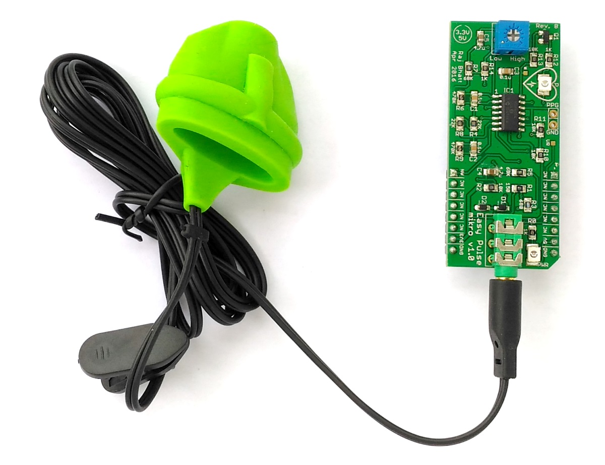
Easy Pulse mikro: A DIY pulse sensor based on transmittance photoplethysmography
Features
- Compatible with mikroBus socket.
- Filtered and amplified analog PPG signal output (range: 0-3.3V).
- On board potentiometer for adjusting amplifier gain, if needed (rotate clock-wise for increasing the gain).
- On board LED for indicating the heart beat. It flashes synchronously with the heart beat on detecting the pulse from fingertip.
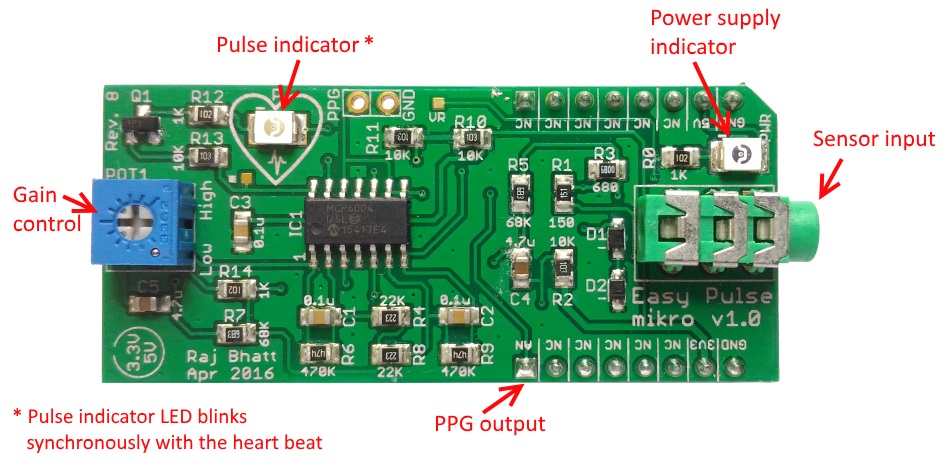
Easy Pulse mikro features (click to enlarge)
The following figure shows an actual PPG output waveform from Easy Pulse mikro. The pulse rate (or heart beat rate) can be computed from the time duration between any two peaks in the signal. This is described in more detail in a demo application provided later in this article.
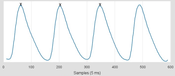
Easy Pulse mikro output PPG waveform
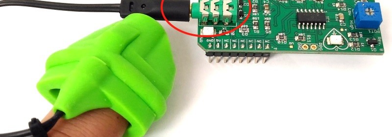
Important note: While operating the pulse sensor, make sure the sensor connector is inserted well and pushed all the way into the audio jack as shown below. During operation, the hand must be in a relaxed position and resting on some solid support for achieving reliable PPG data.
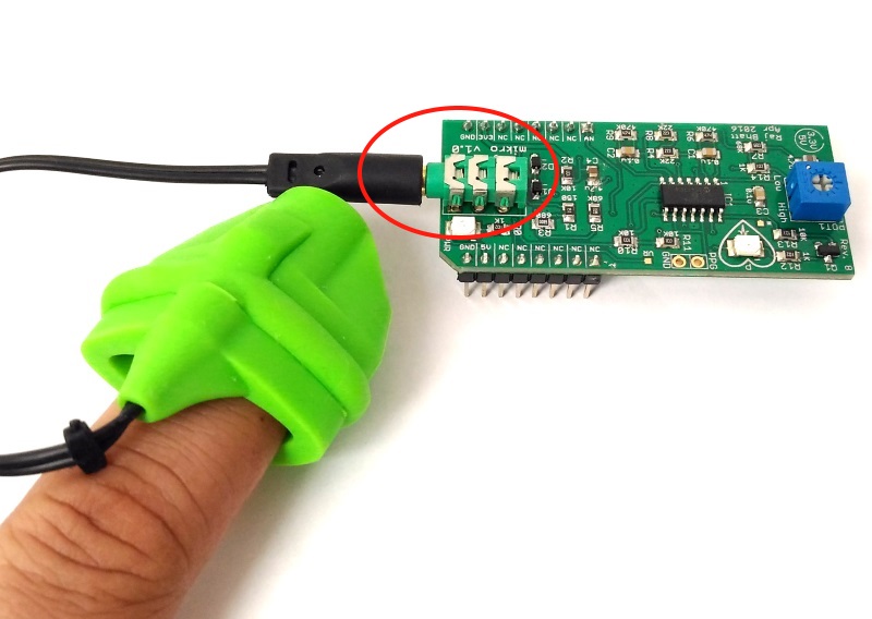
Correct way of inserting the sensor connector in to the board and wearing the sensor on the fingertip.
Demo application
The following demo application shows how to build a stand-alone pulse meter using Easy Pulse mikro and mikroElektronika‘s clicker 2 for PIC18FJ board. An OLED W click board is also used to display the pulse rate in beats per minute (BPM). Following figure shows all the things you would need to build this project.
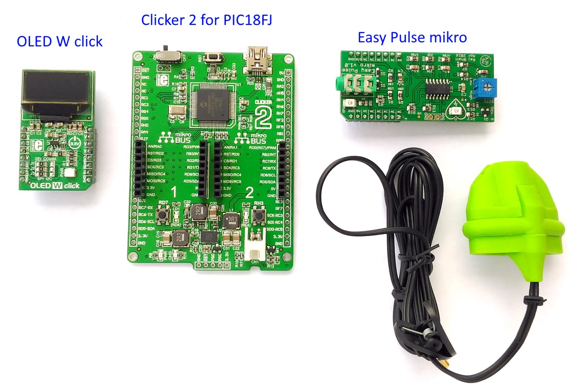
Stand-alone pulse meter using OLED W click, clicker 2 for PIC18FJ, and Easy Pulse mikro sensor
The clicker 2 development board features Microchip’s powerful 8-bit PIC18F87J50 microcontroller, preprogrammed with an USB bootloader, and two mikroBus sockets to receive add-on boards. For this demo project, the OLED W click board is inserted into socket 1 and Easy Pulse mikro to socket 2, as shown below.
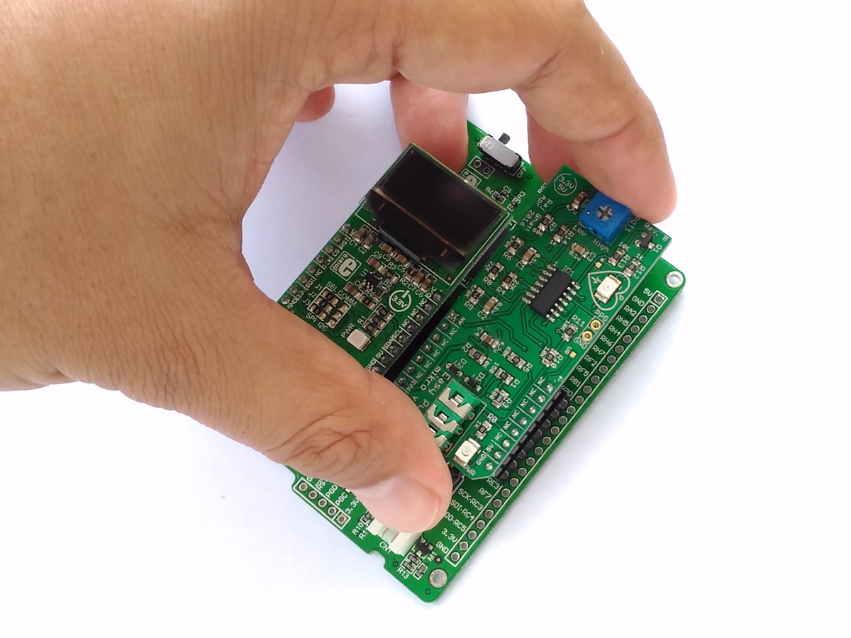
Inserting OLED W click and Easy Pulse mikro into the clicker 2 board
The firmware for this project can be downloaded from the following link. It contains both the source code (written in mikroC Pro for PIC) and HEX file.
Clicker2_PulseMeter_EasyPulse_Firmware
The following flow diagram describes how the pulse rate is computed from the PPG waveform. The PIC microcontroller reads in 600 analog samples of the PPG waveform at 5 millisecond sampling interval and finds three consecutive peaks in the PPG waveform. The pulse rate can then be computed from the time interval between any two successive peaks.

Algorithm to compute heart beat rate
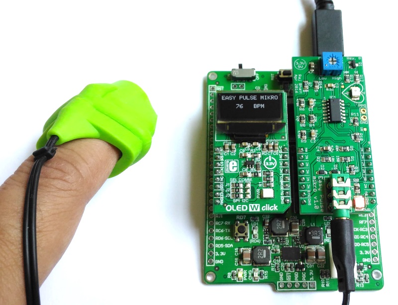
Pulse rate is displayed on the OLED screen
A demo video showing the pulse meter in action.
Buy Easy Pulse mikro from our Chinese store
Buy Easy Pulse mikro from our US store
|
|
Pingback: Easy Pulse mikro – MikroBus form factor pulse sensor - Electronics-Lab