Getting Started with Nuvoton 8-bit Microcontrollers – Coding Part 1
|
|
This post is a continuation of the first post on Nuvoton N76E003 microcontroller here.
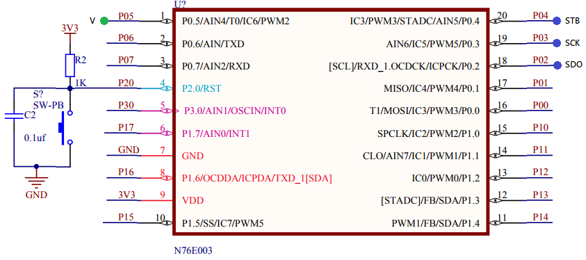
About the N76E006 Test Board
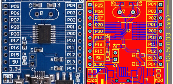
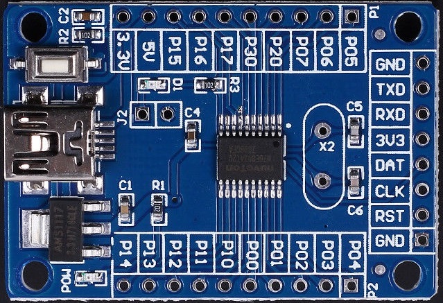
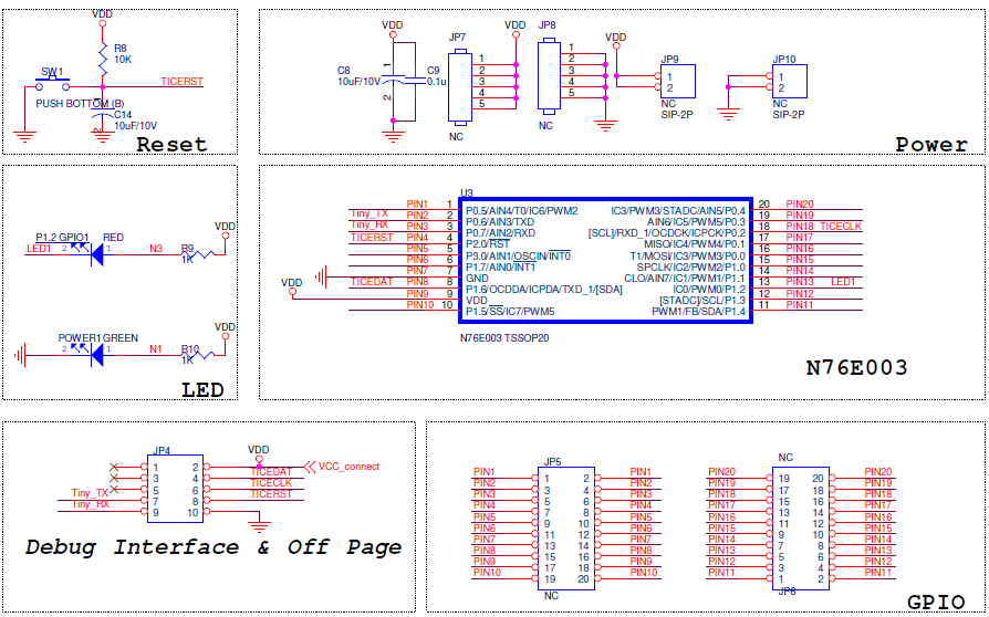
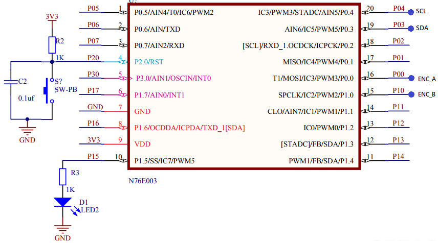
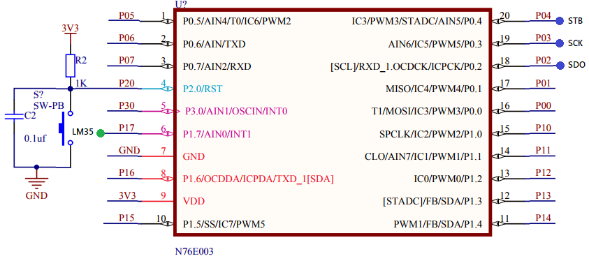
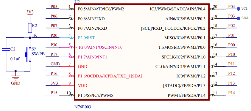
Shown below are the actual photo, the PCB layout and the schematic of the unofficial cheap N76E003 test/development board. This is the board I will be using in this tutorial series.
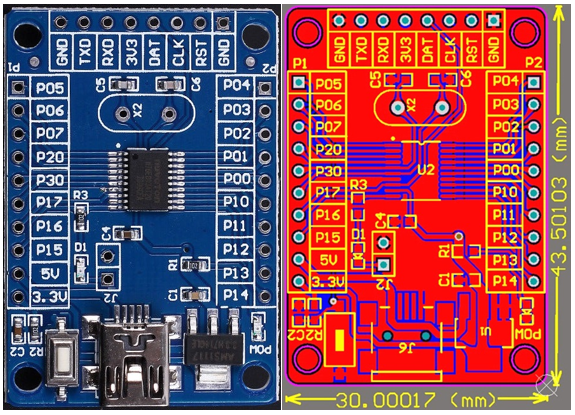
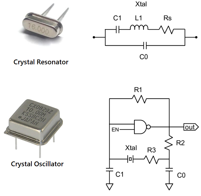
There is nothing much about the 30mm x 43.5mm board. Everything is visible and neat. However, having the schematic alongside the board layout in possession is a great advantage. There are two sidewise header that bring out the GPIO pins and positive supply rails. There is another header opposite to the USB port. This header is for connecting a Nulink programmer-debugger interface and it also has a serial port interface brought out straight from the N76E003 chip. This serial port is useful for quickly debugging/testing stuffs with a serial port monitor. There is an LED connected with P15 pin via a computer jumper. The only thing that is wrong in this board is the crystal resonator part. N76E003 has an external clock input pin but it is meant to be used with active oscillators/crystal modules. In the official, SDK there is no such points to connect an external crystal resonator. The internal high frequency oscillator is accurate enough for most cases.
At this point, I would like to thank Electro Dragon for these images because they are the only ones who shared these resources online.
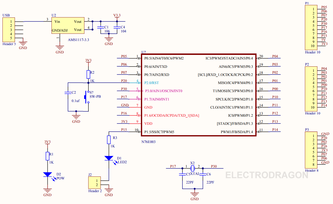
Shown below is the official SDK board’s schematic:
Coding Nuvoton N76E003
When entering a new environment, things are not very easy at first. It takes times to get acquainted with new the new environment, new tools and new stuffs. New means everything different from the ones that you have been using prior to its introduction. In many occasions, I had trouble playing with new microcontrollers due to this. However, after some decent play offs things unfolded themselves.
President JFK’s speech on lunar landing should be an inspirational note for everyone who is trying to do something new or something that he/she has never done before:
We choose to go to the Moon in this decade and do the other things, not because they are easy, but because they are hard; because that goal will serve to organize and measure the best of our energies and skills, because that challenge is one that we are willing to accept, one we are unwilling to postpone, and one we intend to win, and the others, too.
Both Keil and IAR are excellent tools for coding Nuvoton MCUs. I have used both and everything is same in both cases. Literally there is no difference at all. I won’t recommend which one to use and I leave the choice to the readers. However, there are some areas where you may find difficulty porting codes of one compiler to the other. The table below summarizes some of these differences.

Two more things I would like to highlight here. Firstly, both Keil and IAR compiler can throw some errors during code compilations. Most of these errors are due to BSP definitions. One such error is in the line below:
![]()
If you try to use set_P0S_6 definition, IAR sometimes throws an error because it can’t find BIT_TMP. However, there are other similar definitions that don’t throw such error and in Keil you won’t notice something like this. Such things are nasty illogical surprises. We have to understand that the BSPs are still in development. Always remember that the datasheet is your friend. I suggest that when you try out the examples I have shown here, you read the relevant parts of the datasheet to enhance learning and understanding.
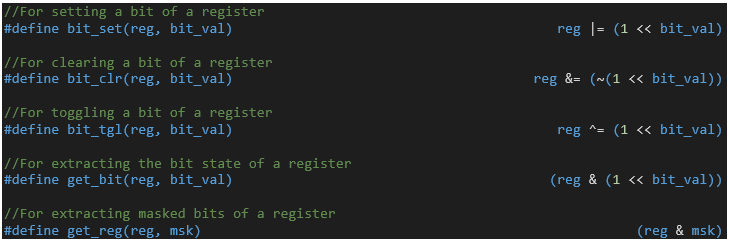
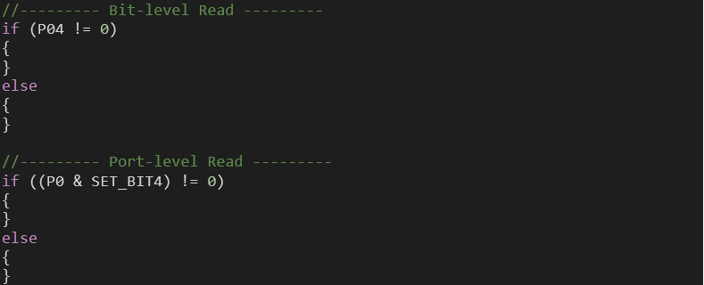
The other thing to note is the fact that not always we have the luxury to avoid register-level coding and so when needed we must have the right knowledge to use them. We can also use bit-level manipulations as shown below:
Sometimes but not always, we have to code things the old ways. Sometimes mixing assembly code with C code becomes a necessity. For instance, the software delay library uses this concept.
There are other aspects to consider too like case sensitivity and coding conventions. It is wise to choose interrupt-driven methods over polling-based ones. Codes should be included in hierarchical orders. Like such there are tons of stuffs to make your code smart and error-free. The best source of knowledge of such things and much more are app notes of various manufacturers.
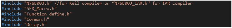
Whenever making a new library, add the followings in your library’s source code along with other header files of your choice to avoid errors and nasty surprises:
Additionally, I have made a set of files called “Extended_Functions”. Here I added all the functions that we will need almost every time when we deal with common internal hardware like timers, ADC, etc. These files are like repositories of all the additional functions that I made for some internal hardware – something that Nuvoton didn’t provide and something that makes coding lot easier. I’ll share these and all the codes with the PDF of the tutorials after Part 2 of this tutorial series.
Here I’m sharing two videos to demonstrate how to code and add custom-made library files in both Keil C51 and IAR Embedded-Workbench compliers.
General Purpose Input-Output (GPIO)
GPIOs are the most common hardware that we use in a microcontroller. Since N76E003 is based on 8051 architecture, we should be getting some similarities with the old school 8051s. Shown below is the hardware schematic of N76E003’s GPIO block:
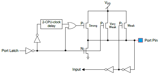
On close inspection, we can realize that this structure has striking resemblance with the GPIO structure of a typical 8051 microcontroller as shown below:
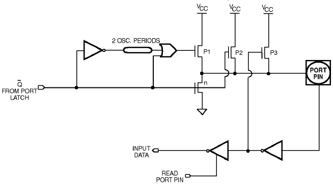
Thus, we can expect similar behaviour.
There are four GPIO modes and these are as follows:
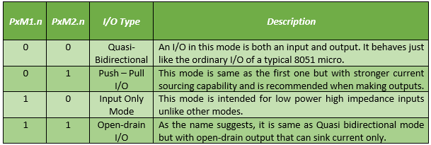
PxM1.n and PxM2.n bits decide these modes. For most cases, we can stick to push-pull and input modes as they are the most commonly used ones.
Code
#include "N76E003_iar.h"
#include "SFR_Macro.h"
#include "Function_define.h"
#include "Common.h"
#include "Delay.h"
void setup(void);
void main(void)
{
setup();
while(1)
{
if(P05 != 0x00)
{
Timer0_Delay1ms(900);
}
set_P15;
Timer0_Delay1ms(100);
clr_P15;
Timer0_Delay1ms(100);
};
}
void setup(void)
{
P15_PushPull_Mode;
P05_Input_Mode;
}
Schematic
Explanation
The Function_define BSP header file states GPIO modes as follows:

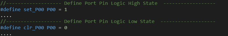
Similarly, SFR_Macro BSP header file defines the bit-level setting of all N76E003 registers. To set the logic level of GPIO pins we can use the following definitions:
However, these don’t restrict us from using classical register-level coding. N76E003 header file states all the registers present in it.
For port/pin reading I didn’t see any function definition as like one I already discussed. Thus, there are two ways to do it on your own. The following as two examples of such:
The demo here is a simple one. The onboard LED connected to P15 pin is toggled at a fixed interval. When a button connected to P05 is pressed the off time of the LED is increased, affecting toggle rate.
Demo

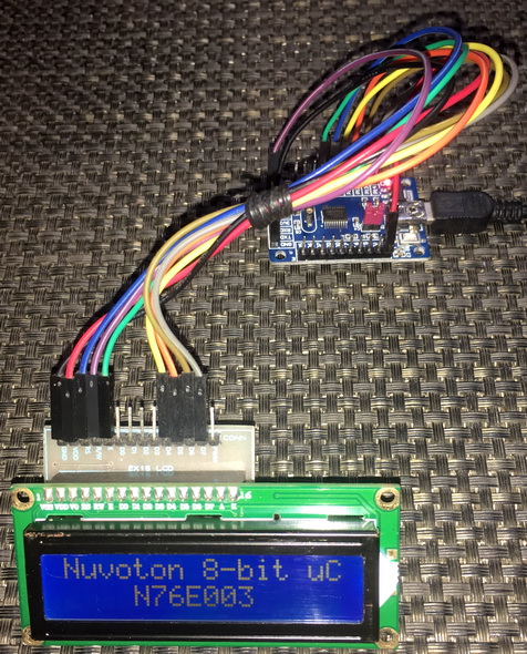
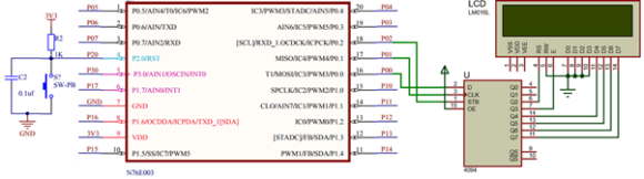
Driving 2×16 LCD
Driving alphanumeric/text LCDs requires no special hardware as simple manipulation of GPIO pins and understanding of their working principle are all that are needed.
Code
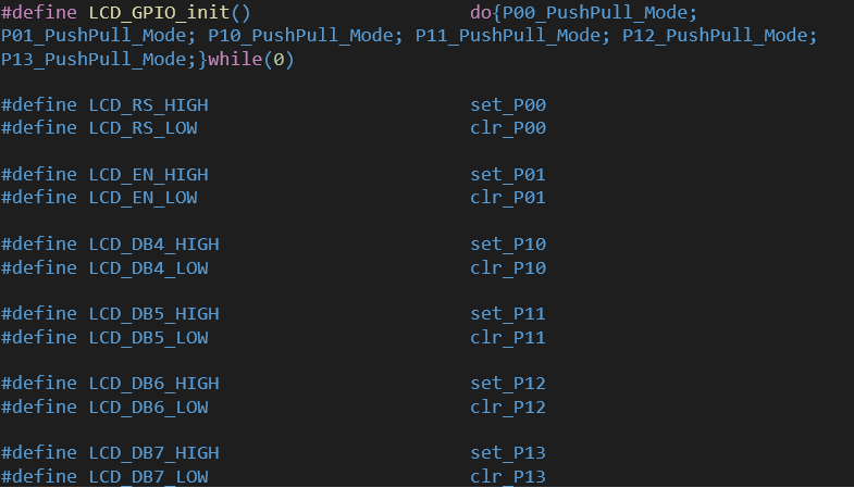
lcd.h
#define LCD_GPIO_init() do{P00_PushPull_Mode; P01_PushPull_Mode; P10_PushPull_Mode; P11_PushPull_Mode; P12_PushPull_Mode; P13_PushPull_Mode;}while(0)
#define LCD_RS_HIGH set_P00
#define LCD_RS_LOW clr_P00
#define LCD_EN_HIGH set_P01
#define LCD_EN_LOW clr_P01
#define LCD_DB4_HIGH set_P10
#define LCD_DB4_LOW clr_P10
#define LCD_DB5_HIGH set_P11
#define LCD_DB5_LOW clr_P11
#define LCD_DB6_HIGH set_P12
#define LCD_DB6_LOW clr_P12
#define LCD_DB7_HIGH set_P13
#define LCD_DB7_LOW clr_P13
#define clear_display 0x01
#define goto_home 0x02
#define cursor_direction_inc (0x04 | 0x02)
#define cursor_direction_dec (0x04 | 0x00)
#define display_shift (0x04 | 0x01)
#define display_no_shift (0x04 | 0x00)
#define display_on (0x08 | 0x04)
#define display_off (0x08 | 0x02)
#define cursor_on (0x08 | 0x02)
#define cursor_off (0x08 | 0x00)
#define blink_on (0x08 | 0x01)
#define blink_off (0x08 | 0x00)
#define _8_pin_interface (0x20 | 0x10)
#define _4_pin_interface (0x20 | 0x00)
#define _2_row_display (0x20 | 0x08)
#define _1_row_display (0x20 | 0x00)
#define _5x10_dots (0x20 | 0x40)
#define _5x7_dots (0x20 | 0x00)
#define DAT 1
#define CMD 0
void LCD_init(void);
void LCD_send(unsigned char value, unsigned char mode);
void LCD_4bit_send(unsigned char lcd_data);
void LCD_putstr(char *lcd_string);
void LCD_putchar(char char_data);
void LCD_clear_home(void);
void LCD_goto(unsigned char x_pos, unsigned char y_pos);
void toggle_EN_pin(void);
lcd.c
#include "N76E003.h"
#include "SFR_Macro.h"
#include "Function_define.h"
#include "Common.h"
#include "Delay.h"
#include "lcd.h"
void LCD_init(void)
{
Timer0_Delay1ms(10);
LCD_GPIO_init();
Timer0_Delay1ms(100);
toggle_EN_pin();
LCD_RS_LOW;
LCD_DB7_LOW;
LCD_DB6_LOW;
LCD_DB5_HIGH;
LCD_DB4_HIGH;
toggle_EN_pin();
LCD_DB7_LOW;
LCD_DB6_LOW;
LCD_DB5_HIGH;
LCD_DB4_HIGH;
toggle_EN_pin();
LCD_DB7_LOW;
LCD_DB6_LOW;
LCD_DB5_HIGH;
LCD_DB4_HIGH;
toggle_EN_pin();
LCD_DB7_LOW;
LCD_DB6_LOW;
LCD_DB5_HIGH;
LCD_DB4_LOW;
toggle_EN_pin();
LCD_send((_4_pin_interface | _2_row_display | _5x7_dots), CMD);
LCD_send((display_on | cursor_off | blink_off), CMD);
LCD_send(clear_display, CMD);
LCD_send((cursor_direction_inc | display_no_shift), CMD);
}
void LCD_send(unsigned char value, unsigned char mode)
{
switch(mode)
{
case DAT:
{
LCD_RS_HIGH;
break;
}
case CMD:
{
LCD_RS_LOW;
break;
}
}
LCD_4bit_send(value);
}
void LCD_4bit_send(unsigned char lcd_data)
{
unsigned char temp = 0;
temp = ((lcd_data & 0x80) >> 7);
switch(temp)
{
case 1:
{
LCD_DB7_HIGH;
break;
}
default:
{
LCD_DB7_LOW;
break;
}
}
temp = ((lcd_data & 0x40) >> 6);
switch(temp)
{
case 1:
{
LCD_DB6_HIGH;
break;
}
default:
{
LCD_DB6_LOW;
break;
}
}
temp = ((lcd_data & 0x20) >> 5);
switch(temp)
{
case 1:
{
LCD_DB5_HIGH;
break;
}
default:
{
LCD_DB5_LOW;
break;
}
}
temp = ((lcd_data & 0x10) >> 4);
switch(temp)
{
case 1:
{
LCD_DB4_HIGH;
break;
}
default:
{
LCD_DB4_LOW;
break;
}
}
toggle_EN_pin();
temp = ((lcd_data & 0x08) >> 3);
switch(temp)
{
case 1:
{
LCD_DB7_HIGH;
break;
}
default:
{
LCD_DB7_LOW;
break;
}
}
temp = ((lcd_data & 0x04) >> 2);
switch(temp)
{
case 1:
{
LCD_DB6_HIGH;
break;
}
default:
{
LCD_DB6_LOW;
break;
}
}
temp = ((lcd_data & 0x02) >> 1);
switch(temp)
{
case 1:
{
LCD_DB5_HIGH;
break;
}
default:
{
LCD_DB5_LOW;
break;
}
}
temp = ((lcd_data & 0x01));
switch(temp)
{
case 1:
{
LCD_DB4_HIGH;
break;
}
default:
{
LCD_DB4_LOW;
break;
}
}
toggle_EN_pin();
}
void LCD_putstr(char *lcd_string)
{
do
{
LCD_send(*lcd_string++, DAT);
}while(*lcd_string != '\0');
}
void LCD_putchar(char char_data)
{
LCD_send(char_data, DAT);
}
void LCD_clear_home(void)
{
LCD_send(clear_display, CMD);
LCD_send(goto_home, CMD);
}
void LCD_goto(unsigned char x_pos, unsigned char y_pos)
{
if(y_pos == 0)
{
LCD_send((0x80 | x_pos), CMD);
}
else
{
LCD_send((0x80 | 0x40 | x_pos), CMD);
}
}
void toggle_EN_pin(void)
{
LCD_EN_HIGH;
Timer0_Delay1ms(4);
LCD_EN_LOW;
Timer0_Delay1ms(4);
}
main.c
#include "N76E003.h"
#include "SFR_Macro.h"
#include "Function_define.h"
#include "Common.h"
#include "Delay.h"
#include "lcd.h"
void show_value(unsigned char value);
void main(void)
{
unsigned char s = 0;
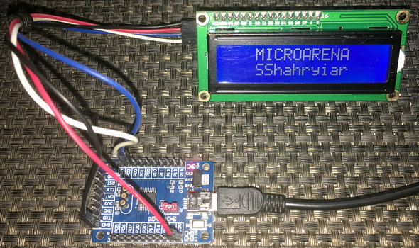
const char txt1[] = {"MICROARENA"};
const char txt2[] = {"SShahryiar"};
const char txt3[] = {"Nuvoton 8-bit uC"};
const char txt4[] = {"N76E003"};
LCD_init();
LCD_clear_home();
LCD_goto(3, 0);
LCD_putstr(txt1);
LCD_goto(3, 1);
LCD_putstr(txt2);
Timer3_Delay100ms(30);
LCD_clear_home();
for(s = 0; s < 16; s++)
{
LCD_goto(s, 0);
LCD_putchar(txt3[s]);
Timer0_Delay1ms(90);
}
Timer3_Delay100ms(20);
for(s = 0; s < 7; s++)
{
LCD_goto((4 + s), 1);
LCD_putchar(txt4[s]);
Timer0_Delay1ms(90);
}
Timer3_Delay100ms(30);
s = 0;
LCD_clear_home();
LCD_goto(3, 0);
LCD_putstr(txt1);
while(1)
{
show_value(s);
s++;
Timer3_Delay100ms(4);
};
}
void show_value(unsigned char value)
{
unsigned char ch = 0x00;
ch = ((value / 100) + 0x30);
LCD_goto(6, 1);
LCD_putchar(ch);
ch = (((value / 10) % 10) + 0x30);
LCD_goto(7, 1);
LCD_putchar(ch);
ch = ((value % 10) + 0x30);
LCD_goto(8, 1);
LCD_putchar(ch);
}
Schematic

Explanation
There is nothing to explain here. The LCD driver is based on simple manipulation of GPIO pins. The codes for the LCD are coded using all available info on LCD datasheet – just initialization and working principle. If you need to change GPIO pins just edit the following lines in the LCD header file:
Demo
Driving 2×16 LCD with Software SPI
One problem with alphanumeric LCDs and GLCDs is the number of GPIOs needed to connect so with host micros. For a small micro like N76E003, each GPIO pin is like a gem and we can’t afford to use too many GPIO pins for an LCD. The solution to this problem is to use SPI/I2C-based LCD drivers that significantly reduce GPIO pin requirement. Implementing software-based SPI/I2C for such LCD drivers is also both easy and universal since these solutions don’t need hardware SPI/I2C ports. Since the SPI/I2C functionality is software emulated, any set of GPIO pins can be used – another advantage.
In this segment, we will be driving a 2×16 LCD with CD4094B Serial-In-Parallel-Out (SIPO) shift register using software SPI. The same idea can be used for other similar shift registers like 74HC595. There are other ways of using SPI-based LCDs but the aforementioned are the cheapest ways.
Code
LCD_3_Wire.h
#define LCD_GPIO_init() do{P02_PushPull_Mode; P03_PushPull_Mode; P04_PushPull_Mode;}while(0)
#define LCD_SDO_HIGH() set_P00
#define LCD_SDO_LOW() clr_P00
#define LCD_SCK_HIGH() set_P01
#define LCD_SCK_LOW() clr_P01
#define LCD_STB_HIGH() set_P02
#define LCD_STB_LOW() clr_P02
#define DAT 1
#define CMD 0
#define clear_display 0x01
#define goto_home 0x02
#define cursor_direction_inc (0x04 | 0x02)
#define cursor_direction_dec (0x04 | 0x00)
#define display_shift (0x04 | 0x01)
#define display_no_shift (0x04 | 0x00)
#define display_on (0x08 | 0x04)
#define display_off (0x08 | 0x02)
#define cursor_on (0x08 | 0x02)
#define cursor_off (0x08 | 0x00)
#define blink_on (0x08 | 0x01)
#define blink_off (0x08 | 0x00)
#define _8_pin_interface (0x20 | 0x10)
#define _4_pin_interface (0x20 | 0x00)
#define _2_row_display (0x20 | 0x08)
#define _1_row_display (0x20 | 0x00)
#define _5x10_dots (0x20 | 0x40)
#define _5x7_dots (0x20 | 0x00)
extern unsigned char data_value;
void SIPO(void);
void LCD_init(void);
void LCD_toggle_EN(void);
void LCD_send(unsigned char value, unsigned char mode);
void LCD_4bit_send(unsigned char lcd_data);
void LCD_putstr(char *lcd_string);
void LCD_putchar(char char_data);
void LCD_clear_home(void);
void LCD_goto(unsigned char x_pos, unsigned char y_pos);
LCD_3_Wire.c
#include "N76E003_iar.h"
#include "SFR_Macro.h"
#include "Function_define.h"
#include "Common.h"
#include "Delay.h"
#include "LCD_3_Wire.h"
unsigned char data_value;
void SIPO(void)
{
unsigned char bit_value = 0x00;
unsigned char clk = 0x08;
unsigned char temp = 0x00;
temp = data_value;
LCD_STB_LOW();
while(clk > 0)
{
bit_value = ((temp & 0x80) >> 0x07);
bit_value &= 0x01;
switch(bit_value)
{
case 0:
{
LCD_SDO_LOW();
break;
}
default:
{
LCD_SDO_HIGH();
break;
}
}
LCD_SCK_HIGH();
temp <<= 0x01;
clk--;
LCD_SCK_LOW();
};
LCD_STB_HIGH();
}
void LCD_init(void)
{
Timer0_Delay1ms(10);
LCD_GPIO_init();
Timer0_Delay1ms(10);
data_value = 0x08;
SIPO();
Timer0_Delay1ms(10);
LCD_send(0x33, CMD);
LCD_send(0x32, CMD);
LCD_send((_4_pin_interface | _2_row_display | _5x7_dots), CMD);
LCD_send((display_on | cursor_off | blink_off), CMD);
LCD_send((clear_display), CMD);
LCD_send((cursor_direction_inc | display_no_shift), CMD);
}
void LCD_toggle_EN(void)
{
data_value |= 0x08;
SIPO();
Timer0_Delay1ms(2);
data_value &= 0xF7;
SIPO();
Timer0_Delay1ms(2);
}
void LCD_send(unsigned char value, unsigned char mode)
{
switch(mode)
{
case DAT:
{
data_value |= 0x04;
break;
}
default:
{
data_value &= 0xFB;
break;
}
}
SIPO();
LCD_4bit_send(value);
}
void LCD_4bit_send(unsigned char lcd_data)
{
unsigned char temp = 0x00;
temp = (lcd_data & 0xF0);
data_value &= 0x0F;
data_value |= temp;
SIPO();
LCD_toggle_EN();
temp = (lcd_data & 0x0F);
temp <<= 0x04;
data_value &= 0x0F;
data_value |= temp;
SIPO();
LCD_toggle_EN();
}
void LCD_putstr(char *lcd_string)
{
while(*lcd_string != '\0')
{
LCD_putchar(*lcd_string++);
}
}
void LCD_putchar(char char_data)
{
if((char_data >= 0x20) && (char_data <= 0x7F))
{
LCD_send(char_data, DAT);
}
}
void LCD_clear_home(void)
{
LCD_send(clear_display, CMD);
LCD_send(goto_home, CMD);
}
void LCD_goto(unsigned char x_pos,unsigned char y_pos)
{
if(y_pos == 0)
{
LCD_send((0x80 | x_pos), CMD);
}
else
{
LCD_send((0x80 | 0x40 | x_pos), CMD);
}
}
main.c
#include "N76E003_iar.h"
#include "SFR_Macro.h"
#include "Function_define.h"
#include "Common.h"
#include "Delay.h"
#include "LCD_3_Wire.h"
void show_value(unsigned char value);
void main(void)
{
unsigned char s = 0;
static char txt1[] = {"MICROARENA"};
static char txt2[] = {"SShahryiar"};
static char txt3[] = {"Nuvoton 8-bit uC"};
static char txt4[] = {"N76E003"};
LCD_init();
LCD_clear_home();
LCD_goto(3, 0);
LCD_putstr(txt1);
LCD_goto(3, 1);
LCD_putstr(txt2);
Timer3_Delay100ms(30);
LCD_clear_home();
for(s = 0; s < 16; s++)
{
LCD_goto(s, 0);
LCD_putchar(txt3[s]);
Timer0_Delay1ms(90);
}
Timer3_Delay100ms(20);
for(s = 0; s < 7; s++)
{
LCD_goto((4 + s), 1);
LCD_putchar(txt4[s]);
Timer0_Delay1ms(90);
}
Timer3_Delay100ms(30);
s = 0;
LCD_clear_home();
LCD_goto(3, 0);
LCD_putstr(txt1);
while(1)
{
show_value(s);
s++;
Timer3_Delay100ms(4);
};
}
void show_value(unsigned char value)
{
unsigned char ch = 0x00;
ch = ((value / 100) + 0x30);
LCD_goto(6, 1);
LCD_putchar(ch);
ch = (((value / 10) % 10) + 0x30);
LCD_goto(7, 1);
LCD_putchar(ch);
ch = ((value % 10) + 0x30);
LCD_goto(8, 1);
LCD_putchar(ch);
}
Schematic
Explanation
The code demoed here is same as the last LCD code and so there is not much to explain. The GPIO operations of the LCD are handled using a CD4094B Serial-In-Parallel-Out (SIPO) shift register. This shift register here acts like an output expander. With just three GPIOs we are able to interface a 4-bit LCD that needs at least six GPIOs to work.
The SIPO function shown below simulates software-based SPI:
void SIPO(void)
{
unsigned char bit_value = 0x00;
unsigned char clk = 0x08;
unsigned char temp = 0x00;
temp = data_value;
LCD_STB_LOW();
while(clk > 0)
{
bit_value = ((temp & 0x80) >> 0x07);
bit_value &= 0x01;
switch(bit_value)
{
case 0:
{
LCD_SDO_LOW();
break;
}
default:
{
LCD_SDO_HIGH();
break;
}
}
LCD_SCK_HIGH();
temp <<= 0x01;
clk--;
LCD_SCK_LOW();
};
LCD_STB_HIGH();
}
To change pins, change the following the lines in the LCD_3_Wire header file:
#define LCD_GPIO_init() do{P02_PushPull_Mode; P03_PushPull_Mode; P04_PushPull_Mode;}while(0)
#define LCD_SDO_HIGH() set_P00
#define LCD_SDO_LOW() clr_P00
#define LCD_SCK_HIGH() set_P01
#define LCD_SCK_LOW() clr_P01
#define LCD_STB_HIGH() set_P02
#define LCD_STB_LOW() clr_P02
Lastly, I have code two versions of this LCD library – one with BSP-based delays and the other with software delays. Technically there’s no big change. The software-based one frees up a hardware timer or two.
Demo
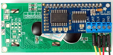
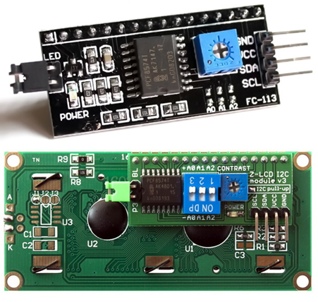
Driving 2×16 LCD with Software I2C
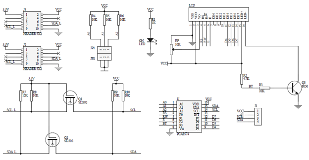
We have already seen in the last segment how to use software SPI with a shift register to drive a 2×16 LCD. In this segment, we will explore the same concept with software I2C and PCF8574 I2C port expander IC. There is a popular readymade module for such task and I used it here. The advantage of I2C-based LCD over SPI-based LCD driver is the lesser number of GPIOs required compared to SPI-based LCD. However, it is slower than SPI-based drivers.
Code
SW_I2C.h
#define SDA_DIR_OUT() P03_PushPull_Mode
#define SDA_DIR_IN() P03_Input_Mode
#define SCL_DIR_OUT() P04_PushPull_Mode
#define SCL_DIR_IN() P04_Input_Mode
#define SDA_HIGH() set_P03
#define SDA_LOW() clr_P03
#define SCL_HIGH() set_P04
#define SCL_LOW() clr_P04
#define SDA_IN() P03
#define I2C_ACK 0xFF
#define I2C_NACK 0x00
#define I2C_timeout 1000
void SW_I2C_init(void);
void SW_I2C_start(void);
void SW_I2C_stop(void);
unsigned char SW_I2C_read(unsigned char ack);
void SW_I2C_write(unsigned char value);
void SW_I2C_ACK_NACK(unsigned char mode);
unsigned char SW_I2C_wait_ACK(void);
SW_I2C.c
#include "N76E003_iar.h"
#include "SFR_Macro.h"
#include "Function_define.h"
#include "Common.h"
#include "Delay.h"
#include "SW_I2C.h"
void SW_I2C_init(void)
{
SDA_DIR_OUT();
SCL_DIR_OUT();
Timer0_Delay100us(1);
SDA_HIGH();
SCL_HIGH();
}
void SW_I2C_start(void)
{
SDA_DIR_OUT();
SDA_HIGH();
SCL_HIGH();
Timer3_Delay10us(4);
SDA_LOW();
Timer3_Delay10us(4);
SCL_LOW();
}
void SW_I2C_stop(void)
{
SDA_DIR_OUT();
SDA_LOW();
SCL_LOW();
Timer3_Delay10us(4);
SDA_HIGH();
SCL_HIGH();
Timer3_Delay10us(4);
}
unsigned char SW_I2C_read(unsigned char ack)
{
unsigned char i = 8;
unsigned char j = 0;
SDA_DIR_IN();
while(i > 0)
{
SCL_LOW();
Timer3_Delay10us(2);
SCL_HIGH();
Timer3_Delay10us(2);
j <<= 1;
if(SDA_IN() != 0x00)
{
j++;
}
Timer3_Delay10us(1);
i--;
};
switch(ack)
{
case I2C_ACK:
{
SW_I2C_ACK_NACK(I2C_ACK);;
break;
}
default:
{
SW_I2C_ACK_NACK(I2C_NACK);;
break;
}
}
return j;
}
void SW_I2C_write(unsigned char value)
{
unsigned char i = 8;
SDA_DIR_OUT();
SCL_LOW();
while(i > 0)
{
if(((value & 0x80) >> 7) != 0x00)
{
SDA_HIGH();
}
else
{
SDA_LOW();
}
value <<= 1;
Timer3_Delay10us(2);
SCL_HIGH();
Timer3_Delay10us(2);
SCL_LOW();
Timer3_Delay10us(2);
i--;
};
}
void SW_I2C_ACK_NACK(unsigned char mode)
{
SCL_LOW();
SDA_DIR_OUT();
switch(mode)
{
case I2C_ACK:
{
SDA_LOW();
break;
}
default:
{
SDA_HIGH();
break;
}
}
Timer3_Delay10us(2);
SCL_HIGH();
Timer3_Delay10us(2);
SCL_LOW();
}
unsigned char SW_I2C_wait_ACK(void)
{
signed int timeout = 0;
SDA_DIR_IN();
SDA_HIGH();
Timer3_Delay10us(1);
SCL_HIGH();
Timer3_Delay10us(1);
while(SDA_IN() != 0x00)
{
timeout++;
if(timeout > I2C_timeout)
{
SW_I2C_stop();
return 1;
}
};
SCL_LOW();
return 0;
}
PCF8574.h
#include "SW_I2C.h"
#define PCF8574_address 0x4E
#define PCF8574_write_cmd PCF8574_address
#define PCF8574_read_cmd (PCF8574_address | 1)
void PCF8574_init(void);
unsigned char PCF8574_read(void);
void PCF8574_write(unsigned char data_byte);
PCF8574.c
#include "N76E003_iar.h"
#include "SFR_Macro.h"
#include "Function_define.h"
#include "Common.h"
#include "Delay.h"
#include "PCF8574.h"
void PCF8574_init(void)
{
SW_I2C_init();
Timer0_Delay1ms(20);
}
unsigned char PCF8574_read(void)
{
unsigned char port_byte = 0;
SW_I2C_start();
SW_I2C_write(PCF8574_read_cmd);
port_byte = SW_I2C_read(I2C_NACK);
SW_I2C_stop();
return port_byte;
}
void PCF8574_write(unsigned char data_byte)
{
SW_I2C_start();
SW_I2C_write(PCF8574_write_cmd);
SW_I2C_ACK_NACK(I2C_ACK);
SW_I2C_write(data_byte);
SW_I2C_ACK_NACK(I2C_ACK);
SW_I2C_stop();
}
LCD_2_Wire.h
#include "PCF8574.h"
#define clear_display 0x01
#define goto_home 0x02
#define cursor_direction_inc (0x04 | 0x02)
#define cursor_direction_dec (0x04 | 0x00)
#define display_shift (0x04 | 0x01)
#define display_no_shift (0x04 | 0x00)
#define display_on (0x08 | 0x04)
#define display_off (0x08 | 0x02)
#define cursor_on (0x08 | 0x02)
#define cursor_off (0x08 | 0x00)
#define blink_on (0x08 | 0x01)
#define blink_off (0x08 | 0x00)
#define _8_pin_interface (0x20 | 0x10)
#define _4_pin_interface (0x20 | 0x00)
#define _2_row_display (0x20 | 0x08)
#define _1_row_display (0x20 | 0x00)
#define _5x10_dots (0x20 | 0x40)
#define _5x7_dots (0x20 | 0x00)
#define BL_ON 1
#define BL_OFF 0
#define dly 2
#define DAT 1
#define CMD 0
void LCD_init(void);
void LCD_toggle_EN(void);
void LCD_send(unsigned char value, unsigned char mode);
void LCD_4bit_send(unsigned char lcd_data);
void LCD_putstr(char *lcd_string);
void LCD_putchar(char char_data);
void LCD_clear_home(void);
void LCD_goto(unsigned char x_pos, unsigned char y_pos);
LCD_2_Wire.c
#include "N76E003_iar.h"
#include "SFR_Macro.h"
#include "Function_define.h"
#include "Common.h"
#include "Delay.h"
#include "LCD_2_Wire.h"
static unsigned char bl_state;
static unsigned char data_value;
void LCD_init(void)
{
PCF8574_init();
Timer0_Delay1ms(10);
bl_state = BL_ON;
data_value = 0x04;
PCF8574_write(data_value);
Timer0_Delay1ms(10);
LCD_send(0x33, CMD);
LCD_send(0x32, CMD);
LCD_send((_4_pin_interface | _2_row_display | _5x7_dots), CMD);
LCD_send((display_on | cursor_off | blink_off), CMD);
LCD_send((clear_display), CMD);
LCD_send((cursor_direction_inc | display_no_shift), CMD);
}
void LCD_toggle_EN(void)
{
data_value |= 0x04;
PCF8574_write(data_value);
Timer0_Delay1ms(1);
data_value &= 0xF9;
PCF8574_write(data_value);
Timer0_Delay1ms(1);
}
void LCD_send(unsigned char value, unsigned char mode)
{
switch(mode)
{
case CMD:
{
data_value &= 0xF4;
break;
}
case DAT:
{
data_value |= 0x01;
break;
}
}
switch(bl_state)
{
case BL_ON:
{
data_value |= 0x08;
break;
}
case BL_OFF:
{
data_value &= 0xF7;
break;
}
}
PCF8574_write(data_value);
LCD_4bit_send(value);
Timer0_Delay1ms(1);
}
void LCD_4bit_send(unsigned char lcd_data)
{
unsigned char temp = 0x00;
temp = (lcd_data & 0xF0);
data_value &= 0x0F;
data_value |= temp;
PCF8574_write(data_value);
LCD_toggle_EN();
temp = (lcd_data & 0x0F);
temp <<= 0x04;
data_value &= 0x0F;
data_value |= temp;
PCF8574_write(data_value);
LCD_toggle_EN();
}
void LCD_putstr(char *lcd_string)
{
do
{
LCD_putchar(*lcd_string++);
}while(*lcd_string != '\0') ;
}
void LCD_putchar(char char_data)
{
if((char_data >= 0x20) && (char_data <= 0x7F))
{
LCD_send(char_data, DAT);
}
}
void LCD_clear_home(void)
{
LCD_send(clear_display, CMD);
LCD_send(goto_home, CMD);
}
void LCD_goto(unsigned char x_pos,unsigned char y_pos)
{
if(y_pos == 0)
{
LCD_send((0x80 | x_pos), CMD);
}
else
{
LCD_send((0x80 | 0x40 | x_pos), CMD);
}
}
main.c
#include "N76E003_iar.h"
#include "SFR_Macro.h"
#include "Function_define.h"
#include "Common.h"
#include "Delay.h"
#include "LCD_2_Wire.h"
void show_value(unsigned char value);
void main(void)
{
unsigned char s = 0;
static char txt1[] = {"MICROARENA"};
static char txt2[] = {"SShahryiar"};
static char txt3[] = {"Nuvoton 8-bit uC"};
static char txt4[] = {"N76E003"};
LCD_init();
LCD_clear_home();
LCD_goto(3, 0);
LCD_putstr(txt1);
LCD_goto(3, 1);
LCD_putstr(txt2);
Timer3_Delay100ms(30);
LCD_clear_home();
for(s = 0; s < 16; s++)
{
LCD_goto(s, 0);
LCD_putchar(txt3[s]);
Timer0_Delay1ms(90);
}
Timer3_Delay100ms(20);
for(s = 0; s < 7; s++)
{
LCD_goto((4 + s), 1);
LCD_putchar(txt4[s]);
Timer0_Delay1ms(90);
}
Timer3_Delay100ms(30);
s = 0;
LCD_clear_home();
LCD_goto(3, 0);
LCD_putstr(txt1);
while(1)
{
show_value(s);
s++;
Timer3_Delay100ms(4);
};
}
void show_value(unsigned char value)
{
unsigned char ch = 0x00;
ch = ((value / 100) + 0x30);
LCD_goto(6, 1);
LCD_putchar(ch);
ch = (((value / 10) % 10) + 0x30);
LCD_goto(7, 1);
LCD_putchar(ch);
ch = ((value % 10) + 0x30);
LCD_goto(8, 1);
LCD_putchar(ch);
}
Schematic

Explanation
Just like the last example, software method is used to emulate I2C protocol using ordinary GPIOs. There are three parts of the code – first the software I2C driver, second the driver library for PCF8574 I2C 8-bit port expander and lastly the LCD driver itself. The LCD driver is same as the other LCD drivers in this document. I kept the code modular so that it is easy to understand the role of each piece of code. The I2C driver (SW_I2C) implements software I2C which is used by the PCF8574 driver. Thus, the port expander driver is dependent on the SW_I2C driver and the LCD driver is dependent on the port expander driver, and in cases like such we must find add libraries according to the order of dependency.
The advantage of keeping things modular is to easily modify things in a fast and trouble-free manner while keeping things ready for other deployments. In my codes I try to avoid repetitive and meaningless stuffs with meaningful definitions. For instance, just change the following lines to change pin configurations without going through the whole code:
#define SDA_DIR_OUT() P03_PushPull_Mode
#define SDA_DIR_IN() P03_Input_Mode
#define SCL_DIR_OUT() P04_PushPull_Mode
#define SCL_DIR_IN() P04_Input_Mode
#define SDA_HIGH() set_P03
#define SDA_LOW() clr_P03
#define SCL_HIGH() set_P04
#define SCL_LOW() clr_P04
#define SDA_IN() P03
Likewise, the SW_I2C functions are not implemented inside the LCD or port expander driver files so that they can be used for other I2C devices.
I have code two versions of this LCD library just like the SPI-based ones – one with BSP-based delays and the other with software delays.
Demo
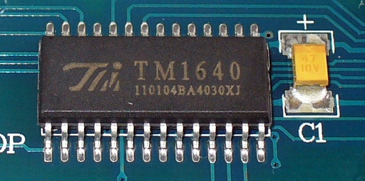
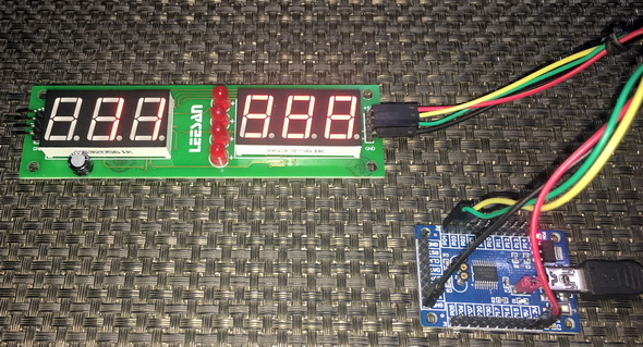
Driving seven Segments by Bit-banging TM1640
Seven segment displays take up lot of GPIO pins when they are required to be interfaced with a host micro. There are several driver ICs like MAX7219, TM1640, 74HC594, etc to overcome this issue. TM1640 from Titan Micro Electronics does not support standard I2C or SPI communication protocol unlike most other driver ICs. Thus, to interface it with our host N76E003 micro, we need to apply bit-banging method just like the LCD examples.
Code
fonts.h
const unsigned char fonts[11] =
{
0x00, // (32) <space>
0x3F, // (48) 0
0x06, // (49) 1
0x5B, // (50) 2
0x4F, // (51) 3
0x66, // (52) 4
0x6D, // (53) 5
0x7D, // (54) 6
0x27, // (55) 7
0x7F, // (56) 8
0x6F, // (57) 9
};
TM1640.h
#define TM1640_GPIO_init() do{P03_PushPull_Mode; P04_PushPull_Mode;}while(0)
#define DIN_pin_HIGH() set_P03
#define DIN_pin_LOW() clr_P03
#define SCLK_pin_HIGH() set_P04
#define SCLK_pin_LOW() clr_P04
#define no_of_segments 16
#define auto_address 0x40
#define fixed_address 0x44
#define normal_mode 0x40
#define test_mode 0x48
#define start_address 0xC0
#define brightness_5_pc 0x88
#define brightness_10_pc 0x89
#define brightness_25_pc 0x8A
#define brightness_60_pc 0x8B
#define brightness_70_pc 0x8C
#define brightness_75_pc 0x8D
#define brightness_80_pc 0x8E
#define brightness_100_pc 0x8F
#define display_off 0x80
#define display_on 0x8F
void TM1640_init(unsigned char brightness_level);
void TM1640_start(void);
void TM1640_stop(void);
void TM1640_write(unsigned char value);
void TM1640_send_command(unsigned char value);
void TM1640_send_data(unsigned char address, unsigned char value);
void TM1640_clear_display(void);
TM1640.c
#include "N76E003.h"
#include "SFR_Macro.h"
#include "Function_define.h"
#include "Common.h"
#include "Delay.h"
#include "TM1640.h"
void TM1640_init(unsigned char brightness_level)
{
TM1640_GPIO_init();
Timer0_Delay1ms(10);
DIN_pin_HIGH();
SCLK_pin_HIGH();
TM1640_send_command(auto_address);
TM1640_send_command(brightness_level);
TM1640_clear_display();
}
void TM1640_start(void)
{
DIN_pin_HIGH();
SCLK_pin_HIGH();
Timer3_Delay10us(1);
DIN_pin_LOW();
Timer3_Delay10us(1);
SCLK_pin_LOW();
}
void TM1640_stop(void)
{
DIN_pin_LOW();
SCLK_pin_LOW();
Timer3_Delay10us(1);
SCLK_pin_HIGH();
Timer3_Delay10us(1);
DIN_pin_HIGH();
}
void TM1640_write(unsigned char value)
{
unsigned char s = 0x08;
while(s > 0)
{
SCLK_pin_LOW();
if((value & 0x01) == 0x01)
{
DIN_pin_HIGH();
}
else
{
DIN_pin_LOW();
}
SCLK_pin_HIGH();
value >>= 0x01;
s--;
};
}
void TM1640_send_command(unsigned char value)
{
TM1640_start();
TM1640_write(value);
TM1640_stop();
}
void TM1640_send_data(unsigned char address, unsigned char value)
{
TM1640_send_command(fixed_address);
TM1640_start();
TM1640_write((0xC0 | (0x0F & address)));
TM1640_write(value);
TM1640_stop();
}
void TM1640_clear_display(void)
{
unsigned char s = 0x00;
for(s = 0x00; s < no_of_segments; s++)
{
TM1640_send_data(s, 0);
};
}
main.c
#include "N76E003.h"
#include "SFR_Macro.h"
#include "Function_define.h"
#include "Common.h"
#include "Delay.h"
#include "font.h"
#include "TM1640.h"
void display_data(unsigned char segment, signed int value);
void main(void)
{
unsigned int i = 0;
unsigned int j = 999;
TM1640_init(brightness_75_pc);;
while(1)
{
display_data(0, i++);
display_data(4, j--);
Timer3_Delay100ms(4);
};
}
void display_data(unsigned char segment, signed int value)
{
unsigned char ch = 0;
if((value > 99) && (value <= 999))
{
ch = (value / 100);
TM1640_send_data((2 + segment), fonts[1 + ch]);
ch = ((value / 10) % 10);
TM1640_send_data((1 + segment), fonts[1 + ch]);
ch = (value % 10);
TM1640_send_data(segment, fonts[1 + ch]);
}
else if((value > 9) && (value <= 99))
{
TM1640_send_data((2 + segment), 0);
ch = (value / 10);
TM1640_send_data((1 + segment), fonts[1 + ch]);
ch = (value % 10);
TM1640_send_data(segment, fonts[1 + ch]);
}
else
{
TM1640_send_data((2 + segment), 0);
TM1640_send_data((1 + segment), 0);
ch = (value % 10);
TM1640_send_data(segment, fonts[1 + ch]);
}
}
Schematic

Explanation
Like the LCD libraries demoed previously, TM1640 is driven with GPIO bit-banging. Please read the datasheet of TM1640 to fully understand how the codes are implemented. It uses two pins just like I2C but don’t be fooled as it doesn’t support I2C protocol. It uses a protocol of its own. To change pin configuration, just change the following lines of code:
#define TM1640_GPIO_init() do{P03_PushPull_Mode; P04_PushPull_Mode;}while(0)
#define DIN_pin_HIGH() set_P03
#define DIN_pin_LOW() clr_P03
#define SCLK_pin_HIGH() set_P04
#define SCLK_pin_LOW() clr_P04
Demo
External Interrupt (EXTI)
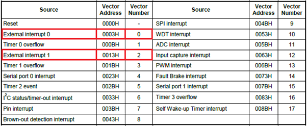
External interrupt is a key GPIO feature in input mode. It momentarily interrupts regular program flow just like other interrupts and does some tasks before resuming interrupted task. In traditional 8051s, there are two external interrupts with dedicated and separate interrupt vector addresses. The same applies to N76E003. Highlighted below in the N76E003’s interrupt vector table are the interrupt vector addresses/numbers of these two external interrupts:
Code
#include "N76E003.h"
#include "SFR_Macro.h"
#include "Function_define.h"
#include "Common.h"
#include "Delay.h"
void setup(void);
void EXT_INT0(void)
interrupt 0
{
set_P00;
}
void EXT_INT1(void)
interrupt 2
{
set_P01;
}
void main(void)
{
setup();
while(1)
{
Timer0_Delay1ms(1000);
clr_P00;
clr_P01;
};
}
void setup(void)
{
P00_PushPull_Mode;
P01_PushPull_Mode;
P17_Input_Mode;
P30_Input_Mode;
set_P1S_7;
set_P3S_0;
set_IT0;
set_IT1;
set_EX0;
set_EX1;
set_EA;
}
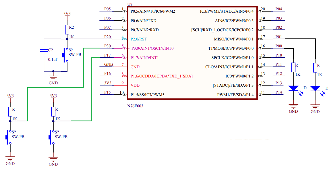
Schematic
Explanation
The setup for this demo is simple. There are two LEDs and two buttons connected with a N76E003 chip as per schematic. The buttons are connected with external interrupt pins. Obviously, these pins are declared as input pins. Additionally, internal input Schmitt triggers of these pins are used to ensure noise cancellation. Both interrupts are enabled along with their respective interrupt hardware. Finally, global interrupt is set. Optionally interrupt priority can be applied.
P17_Input_Mode;
P30_Input_Mode;
set_P1S_7;
set_P3S_0;
set_IT0;
set_IT1;
set_EX0;
set_EX1;
set_EA;
Since we enabled two interrupts with different interrupt vectors, there will be two interrupt subroutine functions. Each of these functions will briefly turn on LEDs assigned to them. The LEDs are turned off in the main function. Thus, the LEDs mark which interrupt occurred.
void EXT_INT0(void)
interrupt 0
{
set_P00;
}
void EXT_INT1(void)
interrupt 2
{
set_P01;
}
Demo
Pin Interrupt – Interfacing Rotary Encoder
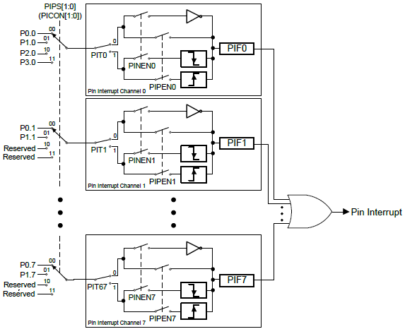
Apart from dedicated external interrupts, N76E003 is equipped with pin interrupt facility – a feature that can be found in almost every microcontroller of modern times. With pin interrupt, any GPIO can be made to behave like external interrupt. However, unlike external interrupts, a single hardware interrupt channel and therefore one vector address is used for mapping a maximum of eight different GPIO pins. These pins need not to be on the same GPIO port. When interrupt occurs, we need to assert from which pin it originated. This feature becomes very useful when interfacing keypads and buttons.
Code
#include "N76E003_IAR.h"
#include "SFR_Macro.h"
#include "Function_define.h"
#include "Common.h"
#include "soft_delay.h"
#include "LCD_2_Wire.h"
signed char encoder_value = 0;
void setup(void);
void lcd_print(unsigned char x_pos, unsigned char y_pos, unsigned int value);
#pragma vector = 0x3B
__interrupt void PIN_INT(void)
{
clr_EA;
if(PIF == 0x01)
{
if((P1 & 0x03) == 0x02)
{
encoder_value++;
}
if(encoder_value > 99)
{
encoder_value = 0;
}
}
if(PIF == 0x02)
{
if((P1 & 0x03) == 0x01)
{
encoder_value--;
}
if(encoder_value < 0)
{
encoder_value = 99;
}
}
PIF = 0x00;
P15 = ~P15;
}
void main(void)
{
setup();
while(1)
{
set_EA;
lcd_print(14, 0, encoder_value);
delay_ms(40);
}
}
void setup(void)
{
P10_Input_Mode;
P11_Input_Mode;
P15_PushPull_Mode;
Enable_BIT0_LowLevel_Trig;
Enable_BIT1_LowLevel_Trig;
Enable_INT_Port1;
set_EPI;
LCD_init();
LCD_clear_home();
LCD_goto(0, 0);
LCD_putstr("ENC Count:");
}
void lcd_print(unsigned char x_pos, unsigned char y_pos, unsigned int value)
{
LCD_goto(x_pos, y_pos);
LCD_putchar((value / 10) + 0x30);
LCD_goto((x_pos + 1), y_pos);
LCD_putchar((value % 10) + 0x30);
}
Schematic
Explanation
Pin interrupt is not same as dedicated external interrupt but still it is very useful in a number of cases. In this demo, two pin interrupts are used to decode a rotary encoder. Probably this is the simplest method of decoding a rotary encoder.
Setting up pin interrupt is very easy. We need to set the pin interrupt pins are inputs. We can optionally use the internal Schmitt triggers. Then we decide the edge to detect and which ports to check for pin interrupt. Finally, we set the pin interrupt hardware.
P10_Input_Mode;
P11_Input_Mode;
Enable_BIT0_LowLevel_Trig;
Enable_BIT1_LowLevel_Trig;
Enable_INT_Port1;
set_EPI;
Inside the pin interrupt function, we need to check which pin shot the interrupt by checking respective flags. Encoder count is incremented/decremented based on which flag got shot first and the logic state of the other pin. Since here a rotary encoder is interfaced with pin interrupt facility of N76E003, we have to ensure that the micro doesn’t detect any further or false interrupts while already processing one interrupt condition. This is why the global interrupt is disabled every time the code enters the pin interrupt function. This is restarted in the main. Similarly, to ensure proper working we have clear the interrupt flags before exiting the function. P15 is toggled with interrupt to visually indicate the rotation of the encoder.
#pragma vector = 0x3B
__interrupt void PIN_INT(void)
{
clr_EA;
if(PIF == 0x01)
{
if((P1 & 0x03) == 0x02)
{
encoder_value++;
}
if(encoder_value > 99)
{
encoder_value = 0;
}
}
if(PIF == 0x02)
{
if((P1 & 0x03) == 0x01)
{
encoder_value--;
}
if(encoder_value < 0)
{
encoder_value = 99;
}
}
PIF = 0x00;
P15 = ~P15;
}
The main code just shows the encoder count. When the encoder is rotated in one direction, the count increases while rotating it in the opposite direction causes the encoder count to decrease.
Demo
Clock System
The clock system of N76E003 is very straight forward and very flexible. To begin with, there are three clock sources, a clock selector and a common clock divider block apart from other blocks. Shown below is the block diagram of N76E003’s clock system:

The three sources are as follows:
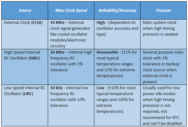
Once a given clock source is set, it becomes the clock for all systems. The only exception here is the watchdog timer and the self-wake-up timer which are only run by the LIRC.
Code
#include "N76E003_iar.h"
#include "SFR_Macro.h"
#include "Function_define.h"
#include "Common.h"
#include "Delay.h"
#define HIRC 0
#define LIRC 1
#define ECLK 2
void set_clock_source(unsigned char clock_source);
void disable_clock_source(unsigned char clock_source);
void set_clock_division_factor(unsigned char value);
void main(void)
{
signed char i = 30;
P11_PushPull_Mode;
P15_PushPull_Mode;
set_clock_division_factor(0);
set_clock_source(HIRC);
set_CLOEN;
while(i > 0)
{
clr_P15;
Timer0_Delay1ms(100);
set_P15;
Timer0_Delay1ms(100);
i--;
}
set_clock_source(ECLK);
disable_clock_source(HIRC);
i = 30;
while(i > 0)
{
clr_P15;
Timer0_Delay1ms(100);
set_P15;
Timer0_Delay1ms(100);
i--;
}
set_clock_source(LIRC);
disable_clock_source(HIRC);
while(1)
{
clr_P15;
Timer0_Delay1ms(1);
set_P15;
Timer0_Delay1ms(1);
};
}
void set_clock_source(unsigned char clock_source)
{
switch(clock_source)
{
case LIRC:
{
set_OSC1;
clr_OSC0;
break;
}
case ECLK:
{
set_EXTEN1;
set_EXTEN0;
while((CKSWT & SET_BIT3) == 0);
clr_OSC1;
set_OSC0;
break;
}
default:
{
set_HIRCEN;
while((CKSWT & SET_BIT5) == 0);
clr_OSC1;
clr_OSC0;
break;
}
}
while((CKEN & SET_BIT0) == 1);
}
void disable_clock_source(unsigned char clock_source)
{
switch(clock_source)
{
case HIRC:
{
clr_HIRCEN;
break;
}
default:
{
clr_EXTEN1;
clr_EXTEN0;
break;
}
}
}
void set_clock_division_factor(unsigned char value)
{
CKDIV = value;
}
Schematic
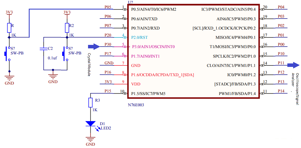
Explanation
The very first thing to note is the absence of two OSC pins unlike other micros and yet a crystal resonator is connected with P30 and P17. This configuration is not correct. There is only OSCIN pin. This is because N76E003 can only be driven with active clock sources like crystal modules, external electronic circuitry, etc. The HIRC clock source is accurate enough for most purposes and there is literally no need for external clock. I have done most of the experiments with HIRC and I’m satisfied with it.
Many people don’t understand the difference between a crystal oscillator module and a crystal resonator. Both are based on quartz crystals but the oscillator one has internal electronics to generate clock pulses precisely while the resonator just contains the quartz crystal. Crystal modules are accurate compared to resonators because the internal electronics in them take care of the effects of temperature. Resonators are therefore called passive clock crystals while the clock modules are termed active clocks.
Here to test all three clock sources, I used two things – first the onboard LED and second the clock output pin. Different clock sources are enabled briefly one after another and the onboard LED is blinked. The blinking rate of the LED is an indirect indicator of clock speed. The clock output too is monitored with an oscilloscope/signal analyser for clock speeds. HIRC is turned on first, then ECLK and finally LIRC. By default, both HIRC and LIRC are turned on during power on. When switching between clock sources, we should poll if the new clock source is stable prior to using it and disable the one that we don’t need.
I have coded the following three for setting up the clock system. Their names suggest their purposes.
void set_clock_source(unsigned char clock_source);
void disable_clock_source(unsigned char clock_source);
void set_clock_division_factor(unsigned char value);
These three functions will be all that you’ll ever need to configure the clock system without any hassle. The first two are most important as they select clock source and disabled the one that is not need. If you are still confused about setting the system clock then you can avoid the clock division function and straight use the following function:
void set_clock_frequency(unsigned long F_osc, unsigned long F_sys)
{
F_osc = (F_osc / (2 * F_sys));
if((F_osc >= 0x00) && (F_osc <= 0xFF))
{
CKDIV = ((unsigned char)F_osc);
}
}
This function takes two parameters – the frequency of the clock source and the frequency of the system after clock division.
Demo
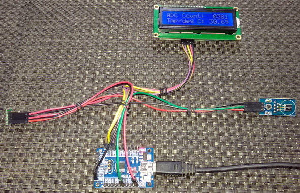
12-Bit ADC – LM35 Thermometer
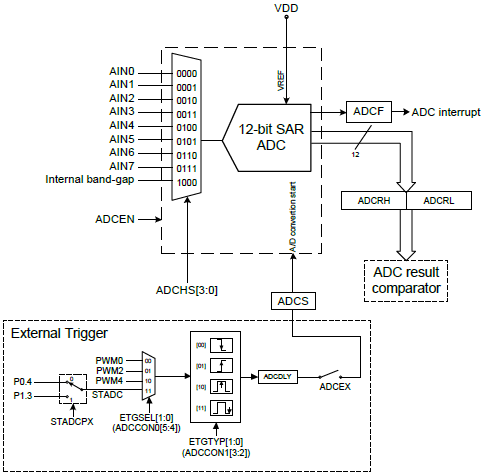
Most 8051s don’t have any embedded ADC but N76E003 comes with a 12-bit SAR ADC. This is also one area where N76E003 differs a lot from STM8S003. The 12-bit resolution is the factor. N76E003 has eight single-ended ADC inputs along with a bandgap voltage generator and a built-in comparator. The ADC can be triggered internally with software or by external hardware pins/PWM. Everything is same as the ADCs of other microcontrollers and there’s not much difference.
Code
#include "N76E003_IAR.h"
#include "SFR_Macro.h"
#include "Function_define.h"
#include "Common.h"
#include "Delay.h"
#include "LCD_3_Wire.h"
#define scalar 0.12412
void setup(void);
unsigned int ADC_read(void);
void lcd_print_i(unsigned char x_pos, unsigned char y_pos, unsigned int value);
void lcd_print_f(unsigned char x_pos, unsigned char y_pos, unsigned int value);
void main(void)
{
unsigned int temp = 0;
unsigned int adc_count = 0;
setup();
while(1)
{
adc_count = ADC_read();
temp = ((unsigned int)(((float)adc_count) / scalar));
lcd_print_i(12, 0, adc_count);
lcd_print_f(11, 1, temp);
Timer0_Delay1ms(600);
}
}
void setup(void)
{
LCD_init();
LCD_clear_home();
LCD_goto(0, 0);
LCD_putstr("ADC Count:");
LCD_goto(0, 1);
LCD_putstr("Tmp/deg C:");
Enable_ADC_AIN0;
}
unsigned int ADC_read(void)
{
register unsigned int value = 0x0000;
clr_ADCF;
set_ADCS;
while(ADCF == 0);
value = ADCRH;
value <<= 4;
value |= ADCRL;
return value;
}
void lcd_print_i(unsigned char x_pos, unsigned char y_pos, unsigned int value)
{
LCD_goto(x_pos, y_pos);
LCD_putchar((value / 1000) + 0x30);
LCD_goto((x_pos + 1), y_pos);
LCD_putchar(((value % 1000) / 100) + 0x30);
LCD_goto((x_pos + 2), y_pos);
LCD_putchar(((value % 100) / 10) + 0x30);
LCD_goto((x_pos + 3), y_pos);
LCD_putchar((value % 10) + 0x30);
}
void lcd_print_f(unsigned char x_pos, unsigned char y_pos, unsigned int value)
{
LCD_goto(x_pos, y_pos);
LCD_putchar((value / 1000) + 0x30);
LCD_goto((x_pos + 1), y_pos);
LCD_putchar(((value % 1000) / 100) + 0x30);
LCD_goto((x_pos + 2), y_pos);
LCD_putchar('.');
LCD_goto((x_pos + 3), y_pos);
LCD_putchar(((value % 100) / 10) + 0x30);
LCD_goto((x_pos + 4), y_pos);
LCD_putchar((value % 10) + 0x30);
}
Schematic
Explanation
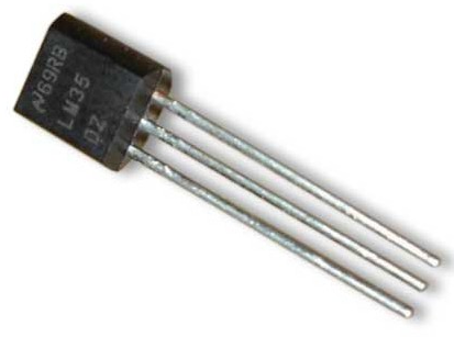
In this demo, one ADC channel (AIN0) is used to read a LM35 temperature sensor. Polling method is used to read the ADC.
Enabling the ADC is simply done by coding the following line:
Enable_ADC_AIN0;
In the background of this, ADC channel selection and other parameters are set. If you want more control over the ADC then you must set the ADC registers on your own. Most of the times that can be avoided.
Reading the ADC needs some attention because the ADC data registers are not aligned like other registers and we just need 12-bits, not 8/16-bits.
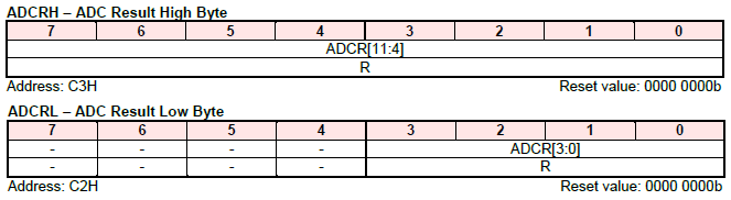
Notice that the we must extract ADC from ADCCRH and from the low four bits of ADCCRL. To handle this issue the follow function is devised:
unsigned int ADC_read(void)
{
register unsigned int value = 0x0000;
clr_ADCF;
set_ADCS;
while(ADCF == 0);
value = ADCRH;
value <<= 4;
value |= ADCRL;
return value;
}
When this function is called, the ADC conversion completion flag is cleared and the ADC is software-triggered. The conversion completion flag is polled. When this flag status is changed, the ADC data registers are read. Finally, the value is returned.
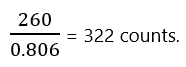
LM35 gives 10mV output for each degree of temperature. Therefore, for 26°C the sensor is supposed to give 260mV output. At 3.3V the ADC count will 4095 while at 0V the ADC count will be 0 count. Thus, 0.806mV equals one count and so 260mV should give:
In the display, we have to show 26.00°C i.e. 2600 considering no decimal point and fully integer value. Thus, to transform 322 to 2600, we have to divide the result with a scalar (0.12412). The main code just does that after reading the ADC. The ADC count and temperature are then both shown in the LCD.
Demo
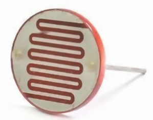
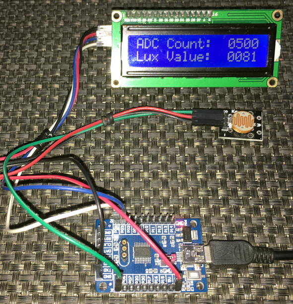
ADC Interrupt – LDR-based Light Sensor
Like any other interrupts, ADC interrupt is a very interrupt. In the last example we saw polling-based ADC readout. In this segment, we will see how to use interrupt-based method to extract ADC data. The concept of ADC interrupt is simply to notify that an ADC data has been made ready for reading once triggered.
Code
#include "N76E003_IAR.h"
#include "SFR_Macro.h"
#include "Function_define.h"
#include "Common.h"
#include "soft_delay.h"
#include "LCD_2_Wire.h"
//LDR Definitions//
#define LDR_constant 100000.0
#define R_fixed 10000.0
#define VDD 4095
unsigned int adc_value = 0x0000;
void setup(void);
unsigned int ADC_read(void);
void lcd_print_i(unsigned char x_pos, unsigned char y_pos, unsigned int value);
unsigned int measure_light_intensity(void);
#pragma vector = 0x5B
__interrupt void ADC_ISR(void)
{
adc_value = ADC_read();
clr_ADCF;
}
void main(void)
{
unsigned int lux = 0;
setup();
while(1)
{
set_ADCS;
lux = measure_light_intensity();
lcd_print_i(12, 0, adc_value);
lcd_print_i(12, 1, lux);
delay_ms(400);
}
}
void setup(void)
{
LCD_init();
LCD_clear_home();
LCD_goto(0, 0);
LCD_putstr("ADC Count:");
LCD_goto(0, 1);
LCD_putstr("Lux Value:");
Enable_ADC_AIN4;
set_EADC;
set_EA;
}
unsigned int ADC_read(void)
{
register unsigned int value = 0x0000;
value = ADCRH;
value <<= 4;
value |= ADCRL;
return value;
}
void lcd_print_i(unsigned char x_pos, unsigned char y_pos, unsigned int value)
{
LCD_goto(x_pos, y_pos);
LCD_putchar((value / 1000) + 0x30);
LCD_goto((x_pos + 1), y_pos);
LCD_putchar(((value % 1000) / 100) + 0x30);
LCD_goto((x_pos + 2), y_pos);
LCD_putchar(((value % 100) / 10) + 0x30);
LCD_goto((x_pos + 3), y_pos);
LCD_putchar((value % 10) + 0x30);
}
unsigned int measure_light_intensity(void)
{
float lux = 0;
lux = adc_value;
lux = (LDR_constant * ((VDD / (R_fixed * lux))) - 0.1);
if((lux >= 0) && (lux <= 9999))
{
return ((unsigned int)lux);
}
else
{
return 0;
}
}
Schematic
Explanation
Setting the ADC in interrupt is not much different from the previous example except for the interrupt parts.
Enable_ADC_AIN4;
set_EADC;
set_EA;
We have to enable both the ADC and global interrupts.
The reading process is also same:
unsigned int ADC_read(void)
{
register unsigned int value = 0x0000;
value = ADCRH;
value <<= 4;
value |= ADCRL;
return value;
}
The ADC is triggered in the main with the following line of code since we are using software-based triggering:
set_ADCS;
Now instead of reading the ADC in the main by polling, the ADC is read in the interrupt.
#pragma vector = 0x5B
__interrupt void ADC_ISR(void)
{
adc_value = ADC_read();
clr_ADCF;
}
When ADC interrupt occurs, we must clear ADC interrupt flag and read the ADC data registers. In this way, the main code is made free from polling and free for other tasks.
The demo here is a rudimentary LDR-based light intensity meter. Light falling on the LDR changes its resistance. Using voltage divider method, we can back calculate the resistance of the LDR and use this info to measure light intensity.
Demo
ADC Comparator
Many micros are equipped with on-chip analogue comparator. N76E003 has an embedded ADC comparator. The main feature of this comparator is the range it offers. Unlike comparators of other micros in which only a few selectable set points can set, the ADC comparator of N76E003 can be set in any range from 0 count to the max ADC count of 4095. This allows us to easily implement it for many applications like low battery alarm, SMPSs, over voltage sense, overload detection, etc. It must be noted however, it is not a true comparator because a true comparator has nothing to do with ADC.
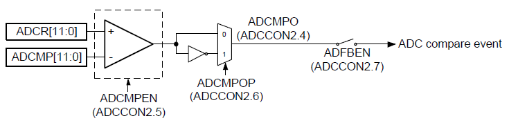
The comparator block is situated at the output of the ADC and so it is just a single block like the ADC but all eight channels share it. Thus, when it is needed to compare multiple channels, it should be reset and reconfigured.
Code
#include "N76E003_IAR.h"
#include "SFR_Macro.h"
#include "Function_define.h"
#include "Common.h"
#include "soft_delay.h"
#include "LCD_2_Wire.h"
unsigned int adc_value = 0x0000;
void setup(void);
unsigned int ADC_read(void);
void set_ADC_comparator_value(unsigned int value);
void lcd_print_i(unsigned char x_pos, unsigned char y_pos, unsigned int value);
#pragma vector = 0x5B
__interrupt void ADC_ISR(void)
{
adc_value = ADC_read();
clr_ADCF;
}
void main(void)
{
setup();
while(1)
{
set_ADCS;
lcd_print_i(12, 0, adc_value);
LCD_goto(12, 1);
if((ADCCON2 & 0x10) != 0x00)
{
LCD_putstr("HIGH");
set_P15;
}
else
{
LCD_putstr(" LOW");
clr_P15;
}
delay_ms(400);
}
}
void setup(void)
{
P15_PushPull_Mode;
LCD_init();
LCD_clear_home();
LCD_goto(0, 0);
LCD_putstr("ADC Count:");
LCD_goto(0, 1);
LCD_putstr("Cmp State:");
Enable_ADC_BandGap;
Enable_ADC_AIN4;
set_ADC_comparator_value(1023);
set_ADCMPEN;
set_EADC;
set_EA;
}
unsigned int ADC_read(void)
{
register unsigned int value = 0x0000;
value = ADCRH;
value <<= 4;
value |= ADCRL;
return value;
}
void set_ADC_comparator_value(unsigned int value)
{
ADCMPH = ((value & 0x0FF0) >> 4);
ADCMPL = (value & 0x000F);
}
void lcd_print_i(unsigned char x_pos, unsigned char y_pos, unsigned int value)
{
LCD_goto(x_pos, y_pos);
LCD_putchar((value / 1000) + 0x30);
LCD_goto((x_pos + 1), y_pos);
LCD_putchar(((value % 1000) / 100) + 0x30);
LCD_goto((x_pos + 2), y_pos);
LCD_putchar(((value % 100) / 10) + 0x30);
LCD_goto((x_pos + 3), y_pos);
LCD_putchar((value % 10) + 0x30);
}
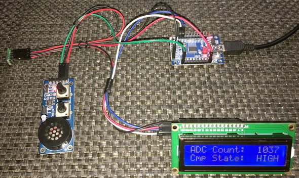
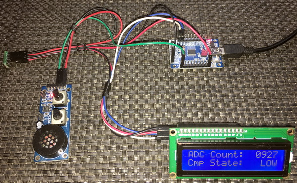
Schematic

Explanation
To configure the ADC comparator block, we just need to specify two things – the reference value with which the comparison should to be done and the polarity of comparison. After setting these up, we have to enable the comparator block. These are done as follows:
set_ADC_comparator_value(1023);
set_ADCMPEN;
Note in the code snippet above, I didn’t code anything regarding polarity because by default the polarity is set as such that the comparator’s output will change state when the input voltage is greater than or equal to the set ADC count level of 1023.
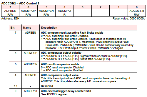
Just like ADC reading, we have to take care of the bit positions for the comparator set point. It is coded as follows.
void set_ADC_comparator_value(unsigned int value)
{
ADCMPH = ((value & 0x0FF0) >> 4);
ADCMPL = (value & 0x000F);
}
In this demo, I also used the bandgap voltage as reference source:
Enable_ADC_BandGap;
The rest of the code is similar to the ADC interrupt code.
Demo
Data Flash – Using APROM as EEPROM
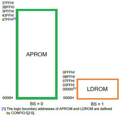
In most standard 8051s, there is no dedicated memory space as EEPROM. This is unlike other microcontrollers of modern era. EEPROM memory is needed for the storage of critical data that need to be retained even in power down state. In N76E003, there are two types of ROM memory. EEPROM-like storage can be achieved by using APROM (Application ROM). APROM is the actual flash memory where store our application codes. User Code Loader ROM or LDROM of N76E003 microcontroller, is another ROM where we can keep a bootloader and configuration codes. Sizes of these ROMs can be varied according to configuration bits.
Code
Flash.h
#define CID_READ 0x0B
#define DID_READ 0x0C
#define PAGE_ERASE_AP 0x22
#define BYTE_READ_AP 0x00
#define BYTE_PROGRAM_AP 0x21
#define PAGE_SIZE 128u
#define ERASE_FAIL 0x70
#define PROGRAM_FAIL 0x71
#define IAPFF_FAIL 0x72
#define IAP_PASS 0x00
void enable_IAP_mode(void);
void disable_IAP_mode(void);
void trigger_IAP(void);
unsigned char write_data_to_one_page(unsigned int u16_addr, const unsigned char *pDat, unsigned char num);
void write_data_flash(unsigned int u16_addr, unsigned char *pDat, unsigned int num);
void read_data_flash(unsigned int u16_addr, unsigned char *pDat, unsigned int num);
Flash.c
#include "N76E003_iar.h"
#include "SFR_Macro.h"
#include "Function_define.h"
#include "Common.h"
#include "Delay.h"
#include "soft_delay.h"
#include "Flash.h"
static unsigned char EA_Save_bit;
void enable_IAP_mode(void)
{
EA_Save_bit = EA;
clr_EA;
TA = 0xAA;
TA = 0x55;
CHPCON |= 0x01 ;
TA = 0xAA;
TA = 0x55;
IAPUEN |= 0x01;
EA = EA_Save_bit;
}
void disable_IAP_mode(void)
{
EA_Save_bit = EA;
clr_EA;
TA = 0xAA;
TA = 0x55;
IAPUEN &= ~0x01;
TA = 0xAA;
TA = 0x55;
CHPCON &=~ 0x01;
EA = EA_Save_bit;
}
void trigger_IAP(void)
{
EA_Save_bit = EA;
clr_EA;
TA = 0xAA;
TA = 0x55;
IAPTRG |= 0x01;
EA = EA_Save_bit;
}
unsigned char write_data_to_one_page(unsigned int u16_addr, const unsigned char *pDat, unsigned char num)
{
unsigned char i = 0;
unsigned char offset = 0;
unsigned char __code *pCode;
unsigned char __xdata *xd_tmp;
enable_IAP_mode();
offset = (u16_addr & 0x007F);
i = (PAGE_SIZE - offset);
if(num > i)
{
num = i;
}
pCode = (unsigned char __code *)u16_addr;
for(i = 0; i < num; i++)
{
if(pCode[i] != 0xFF)
{
break;
}
}
if(i == num)
{
IAPCN = BYTE_PROGRAM_AP;
IAPAL = u16_addr;
IAPAH = (u16_addr >> 8);
for(i = 0; i < num; i++)
{
IAPFD = pDat[i];
trigger_IAP();
IAPAL++;
}
for(i = 0; i < num; i++)
{
if(pCode[i] != pDat[i])
{
break;
}
}
if(i != num)
{
goto WriteDataToPage20;
}
}
else
{
WriteDataToPage20:
pCode = (unsigned char __code *)(u16_addr & 0xFF80);
for(i = 0; i < 128; i++)
{
xd_tmp[i] = pCode[i];
}
for(i = 0; i < num; i++)
{
xd_tmp[offset + i] = pDat[i];
}
do
{
IAPAL = (u16_addr & 0xFF80);
IAPAH = (u16_addr >> 8);
IAPCN = PAGE_ERASE_AP;
IAPFD = 0xFF;
trigger_IAP();
IAPCN =BYTE_PROGRAM_AP;
for(i = 0; i < 128; i++)
{
IAPFD = xd_tmp[i];
trigger_IAP();
IAPAL++;
}
for(i = 0; i < 128; i++)
{
if(pCode[i] != xd_tmp[i])
{
break;
}
}
}while(i != 128);
}
disable_IAP_mode();
return num;
}
void write_data_flash(unsigned int u16_addr, unsigned char *pDat,unsigned int num)
{
unsigned int CPageAddr = 0;
unsigned int EPageAddr = 0;
unsigned int cnt = 0;
CPageAddr = (u16_addr >> 7);
EPageAddr = ((u16_addr + num) >> 7);
while(CPageAddr != EPageAddr)
{
cnt = write_data_to_one_page(u16_addr, pDat, 128);
u16_addr += cnt;
pDat += cnt;
num -= cnt;
CPageAddr = (u16_addr >> 7);
}
if(num)
{
write_data_to_one_page(u16_addr, pDat, num);
}
}
void read_data_flash(unsigned int u16_addr, unsigned char *pDat, unsigned int num)
{
unsigned int i = 0;
for(i = 0; i < num; i++)
{
pDat[i] = *(unsigned char __code *)(u16_addr+i);
}
}
main.c
#include "N76E003_IAR.h"
#include "Common.h"
#include "Delay.h"
#include "soft_delay.h"
#include "SFR_Macro.h"
#include "Function_define.h"
#include "LCD_2_Wire.h"
#include "Flash.h"
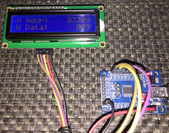
#define BASE_ADDRESS 3700
void lcd_print_c(unsigned char x_pos, unsigned char y_pos, unsigned char value);
void lcd_print_i(unsigned char x_pos, unsigned char y_pos, unsigned int value);
void main (void)
{
unsigned char s = 0;
unsigned char val[1] = {0};
unsigned char ret_val[1] = {0};
P15_PushPull_Mode;
LCD_init();
LCD_clear_home();
clr_P15;
LCD_goto(0, 0);
LCD_putstr("R Addr:");
LCD_goto(0, 1);
LCD_putstr("R Data:");
for(s = 0; s <= 9; s++)
{
read_data_flash((s + BASE_ADDRESS), ret_val, 1);
delay_ms(10);
lcd_print_i(11, 0, (s + BASE_ADDRESS));
lcd_print_c(13, 1, ret_val[0]);
delay_ms(600);
}
delay_ms(2000);
set_P15;
LCD_goto(0, 0);
LCD_putstr("W Addr:");
LCD_goto(0, 1);
LCD_putstr("W Data:");
for(s = 0; s <= 9; s++)
{
val[0] = s;
write_data_flash((s + BASE_ADDRESS), val, 1);
delay_ms(10);
lcd_print_i(11, 0, (s + BASE_ADDRESS));
lcd_print_c(13, 1, val[0]);
delay_ms(600);
}
while(1)
{
};
}
void lcd_print_c(unsigned char x_pos, unsigned char y_pos, unsigned char value)
{
LCD_goto(x_pos, y_pos);
LCD_putchar((value / 100) + 0x30);
LCD_goto((x_pos + 1), y_pos);
LCD_putchar(((value % 10) / 10) + 0x30);
LCD_goto((x_pos + 2), y_pos);
LCD_putchar((value % 10) + 0x30);
}
void lcd_print_i(unsigned char x_pos, unsigned char y_pos, unsigned int value)
{
LCD_goto(x_pos, y_pos);
LCD_putchar((value / 10000) + 0x30);
LCD_goto((x_pos + 1), y_pos);
LCD_putchar(((value % 10000) / 1000) + 0x30);
LCD_goto((x_pos + 2), y_pos);
LCD_putchar(((value % 1000) / 100) + 0x30);
LCD_goto((x_pos + 3), y_pos);
LCD_putchar(((value % 100) / 10) + 0x30);
LCD_goto((x_pos + 4), y_pos);
LCD_putchar((value % 10) + 0x30);
}
Schematic
Explanation
To write and read data from flash we can use the following functions:
void write_data_flash(unsigned int u16_addr, unsigned char *pDat, unsigned int num);
void read_data_flash(unsigned int u16_addr, unsigned char *pDat, unsigned int num);
Both of these functions are pointer-based functions. The first parameter of these function is the physical location of data, the second argument is the data pointer itself and the last argument is the number of bytes to read/write. Try to use the upper addresses of the flash where application code usually doesn’t reside. Reading the flash doesn’t require any involvement of IAP while writing does require IAP. The functions are self-explanatory and can be used readily without any changes since they are provided in the BSP examples.
In the demo, ten data bytes are saved in ten separate locations starting from location 3700 to 3709. Prior to that these locations are read. On first start up, these locations have no saved data and so they show up garbage values (205/255 usually). When a valid user data is saved, the location is updated with it. When reset or powered down, the newly written data bytes are retained and reread when powered up again.
Try not to frequently write on the flash since flash memories wear on frequent writes. Use a RAM-based buffer and try to write one page of flash when the buffer is full. In this way, flash memory wear-and-tear is slightly reduced.
Be careful about saving locations. Don’t use locations that hold application code. Try to use unoccupied empty flash locations or upper flash addresses. Use the NuMicro ISP Programming Tool for finding empty locations.
Demo
|
|
hello
i want to put a bootloader into LDROM so that i could program n76e003at20 through serial port.
could you help me or guide me.
thanks
https://www.instructables.com/Charlieplexing-7-segment-displays-1/
Dear Sir, can you please help me Charlie Pixeled 4 digit display so that just using 9 pins we can drive 8 digits of seven segment display.
it’ll be very helpful for my projects.
Great effort . Greatly appreciated!!!!!! Old school c code very good!!!
Hi,
Can u provide code for 3phase 3wire detection where ac input sense at pin 1,2,3 as adc and DC shifted for 10 bit adc. Means zero crossing happens at 512.
Hi,
Good day. Do you have code for N76E003AT20 to find Phase Sequence, Where R, Y, B sensing is superimpose on 2 volt DC line. I think it was done for PIC16F873A during Dec 2015 by you.
Regards
A shah
How to interface N76E003AT20 with 4 Digit 7 Segment Display? Can you please make one blog I cant find any resource online.
Hello ,
Thank you for the very useful tutorial.
Is there anyway to set the CONFIG0 byte ? Specifically I want to set the LOCK bit after programming the IC.
Thanks !
byte CONFIG0 can config when your programming, if you use IDE KeilC you can config ist at tab taget-> debug, at here you can config registers CONFIG0, if you use application Numicro ICP Programming Toll you can config at tab setting when connect IC with application.
Hi,
Good day . Is there ADC prescaler facility in N76E003AT20?
Regards
Hi Shawon,
I have problém with SCL1602Q display. It wont work. But there Is also PCF8574T chip. Where can be a problem?
Thank you a lot for this N76E003 projects!
Mark
I am developing a board using MS51FB9AE. I write and read 32 bit to eeprom, but i have a problem i couldn’t solve it can you help me ? I added more capacitors to the 5v supply line.
eeprom write code not spinning constantly while in software. I can read and write smoothly, but sometimes forgets.
My read and write code;
void memory_write(void)
{
unsigned char temp1;
unsigned char temp2;
unsigned char temp3;
temp1 = reset_sayac;
Write_DATAFLASH_BYTE(0x3800, temp1);
temp1 = reset_sayac >> 8;
Write_DATAFLASH_BYTE(0x3801, temp1);
temp1 = reset_sayac >> 16;
Write_DATAFLASH_BYTE(0x3802, temp1);
temp1 = reset_sayac >> 24;
Write_DATAFLASH_BYTE(0x3803, temp1);}
//*****************
void memory_read(void)
{
reset_sayac = Read_APROM_BYTE(0x3803);
reset_sayac <<= 8;
reset_sayac += Read_APROM_BYTE(0x3802);
reset_sayac <<= 8;
reset_sayac += Read_APROM_BYTE(0x3801);
reset_sayac <<= 8;
reset_sayac += Read_APROM_BYTE(0x3800);}
Hi, i’m learning with Nuvoton W78E052D 40pin DIP IC. Could you please help me on how to lock the chip. Its said in datasheet page 66. But i could not program the CONFIG BITS.
Its saying SPECIAL SETTING REGISTER location no #FFFFh. How to access that location using UART programmer.
I’m using Nuvoton ISP-ICP utility software. When i choose W78E052 chip, the configuration icon / button disable automatically.
Thanks
Why in Driving 2×16 LCD example PINs D0 to D3 are not connected and not used in program?
because the LCD was coded to use 4-bit mode instead of 8-bit mode…. In 8-bit mode pins D0 to D3 are needed….
thank you
Hi,
Good day.
Do you have example of N76E003AT20 with Nextion NX3224K028?
Regards
no….
OK. Thank You.
What is the way to move forward with Nextion NX3224K028.?
Please suggest if any.
Regards
Let’s say I have a loop with a variable “i” that is read by the number of button presses on one of the inputs. Is it possible to write this “i” to memory so that after power off, this “i” has the same value as before power off?
sounds possible but at the cost of frequent wear & tear of the memory….
it will be just a time realy. I want set dealy in seconds on LED display and keep this tine ib the memory even after power cycle. How to do that?
can anyone help me to measure phase diffrence between ac voltage and current using adc and timer3 i AMusing 32 pin MS51PC0AE Nuvoton microcontrollers ?
I needs example code assembly for comunication serial the nuvoton 76E003 to IHM delta modbus rs485, please help me!
I needs a example code assembly for comunications serial the nuvoton 76E003 with IHM delta modbus rs485
Hi.. I have been trying to interface I2C with nuvoton N76E003, I have copied the c code in my keil software and I have copied the h files in include folder. But I am not able to see the text getting displayed on the screen of my I2C display.
Hi Sir
I am, Try to some Read and Write some value ( its signed char ) in EEPROM. but It’s Not Working Properly.
will write value with help of Push button. after write the value in eeprom, my harware not working
Will #define BASE_ADDRESS = 3700
as per UR pdf document, how to find out unoccupied empty flash locations or upper flash addresses ?
after compiling getting >>
Program Size: data=93.1 xdata=0 code=6340
“.\Objects\7_Segment_DS1820” – 0 Error(s), 0 Warning(s).
Hi, Same issue, did u get the solution pls share.
Hi all,
I’m using MS51FC0AE, in which not able to store data.
once restarted data will be lost and filled with 0xFF.
————————————————————————————————————————————————-
Write_DATAFLASH_ARRAY(0x3800,(unsigned char *)&StructData,sizeof(StructData));//write structure
system16highsite = Read_APROM_BYTE((unsigned int __code *)0x3800);
————————————————————————————————————————————————-
void Write_DATAFLASH_ARRAY(unsigned int u16_addr,unsigned char *pDat,unsigned int num)
{
unsigned char CPageAddr,EPageAddr,cnt;
CPageAddr=u16_addr>>7;
EPageAddr=(u16_addr+num)>>7;
while(CPageAddr!=EPageAddr)
{
cnt=WriteDataToOnePage(u16_addr,pDat,128);
u16_addr+=cnt;
pDat+=cnt;
num-=cnt;
CPageAddr=u16_addr>>7;
}
if(num)
{
WriteDataToOnePage(u16_addr,pDat,num);
}
}
//————————————————————————-
void Read_DATAFLASH_ARRAY(unsigned int u16_addr,unsigned char *pDat,unsigned int num)
{
unsigned int i;
for(i=0;i<num;i++)
pDat[i] = (*(unsigned char __code *)(u16_addr+i));
}
what might be the issue?
I need your help how to increase data memory keil c51 show 128 only datasheet show 1kb , the results show data too large full, any idea
Change memory model….
Hello Sir,
please help for my counter program,
I want to store 4 different values which are set by incrementing or decrementing it in EEPROM memory. so that these selected values remain stored even if power is Off, and these values are restored again on powering On this microcontroller.
Please help me on this
N76E003 could be easily flashed using CH341 programmer, using NeoProgrammer software (v2.2.0.x required).
Hello sir ,
I want to write a bootloader code in ldrom to program controller through uart or spi.
Pingback: Refurbishing a servo tester – ydiaeresis
Thanks For the tutorials.
Do you have tutorial for N76E003 with HC05?
Regards,
A Shah
Sir,
Im using keil v5 for n76e003 and need help in code for ADC being potentiometer as input and LED as output.
Hi Sir
i have need some help to, use P2.0 (RST) Pin as Switch Input
HOW to Define P2.0 As Input
Use the ICP Programming tool. Go to settings and select P2.0 option.
Than’k Sir
Shawon Shahryiar , could you pls explain how to dump a code in the n76 controller in nu link connection section or give any article link to study nu link programmer connection to n76 ic pinout connection
The connection between N76E003 and Nu-Link is simple. Just connect VDD, GND, RST, CLK and DAT.
EVER TRIED ONE WIRE (SPI) DRIVEN NEOPIXEL ?
I’M TRYING WITH TIMER_3 BUT NOT GETTING SPECIFIC TIMING PULSES.
It won’t work because unlike other microcontrollers, the idle state of MOSI pin in N76E003 is high instead of low….
its not actual SPI.
its software defined pulse accordingly time, all i need to do is get pulse in neno-second precisely it will works
I know it is not actual SPI and SPI hardware won’t help in this matter….
Need help on how to made ready N76E003 microcontroller for first time to get it programm and by which hardware?
Read this
Hi to all.Anybody help me in getting started with N76E003 microcontroller.My problem is.we get some board readymade from vendor with Nuvoton N76e controller fixed and programmed.Also we get some hardware from vendor to reprogram the controller as per out input.Now we made Our PCB and arrange controller from market.This controller is not getting programmed.Anybody guide me how to program the microcontroller from given hardware. Mail-id. vimeshsharma@gmail.com.
Use NuMicro ICP Programming Tool….
Dear sir,
i am working on N76E003 microcontroller and Max6675, i had attached lcd and make my pcb. my pcb and connections are ok. but it gives same temprature reading every time even i heat probe of thrmocouple, and on reset it shows currect reading, my code as bellow
#include “N76E003.h”
#include “SFR_Macro.h”
#include “Function_define.h”
#include “Common.h”
#include “Delay.h”
#include “lcd.h”
#include “soft_delay.h”
#include “MAX6675.h”
//#include “Flash.h”
//functions defined
void setup(void);
void show_value(unsigned char value, int row);
//void coinrecived(void);
unsigned int avalable, napkin;
int cnt;
const char txt3[] = {“SET TEMP “};
const char txt4[] = {“ACTUAL TEMP “};
const char txt6[] = {“BURNING…”};
// const char txt5[] = {” “};
void main(void)
{
unsigned char state = close_contact;
unsigned int ti = 0x0000;
unsigned int t = 0;
const char txt1[] = {“PADS IN “};
const char txt2[] = {“…”};
P15_PushPull_Mode;
MAX6675_init();
setup();
LCD_init();
LCD_clear_home();
LCD_goto(0, 0);
LCD_putstr(txt1);
LCD_goto(0, 1);
LCD_putstr(txt2);
avalable= 1;
// set_P01;
if(avalable!=0) ///Empty
{
}
while(1)
{
//unsigned char state = open_contact;
P15 = 1;
clr_CPOL;
set_CPHA;
state = MAX6675_get_ADC(&ti);
t = ((unsigned int)MAX6675_get_T(ti, tmp_K));
delay_ms(100);
P15 = 0;
clr_CPOL;
clr_CPHA;
//set_SPIF;
delay_ms(100);
//LCD_clear_home();
show_value(t, 0);
show_value(ti, 1);
P04= ~P04;
SPDR=0x00;
////////////////////////////////////////
}
}
void show_value(unsigned char value, int row) /////////show on lcd
{
unsigned char ch = 0x00;
//value=123;
ch = ((value / 100) + 0x30);
LCD_goto(13, row);
LCD_putchar(ch);
ch = (((value / 10) % 10) + 0x30);
LCD_goto(14, row);
LCD_putchar(ch);
ch = ((value % 10) + 0x30);
LCD_goto(15, row);
LCD_putchar(ch);
}
void setup(void) ////////setup
{
// P12_PushPull_Mode;
P04_PushPull_Mode;
//P01_PushPull_Mode;
// P17_Input_Mode;
//P30_Input_Mode;
//set_P1S_7; // Schmitt Triggered Input p17
// set_P3S_0; // Schmitt Triggered Input p13
//set_IT0; // 0is low level triggered.
// 1 is falling edge triggered.
//set_IT1;
// set_EX0; // Enable external interrupt 1
// clr_EX1;
set_EA; //Enable all interrupt
}
Sounds to me an issue with CPOL and CPHA…. Try altering these….
Hi Sir
T hank’s for Great Tutorial,
I am Try to int TM1637 To MCU using TM1640 Lib.Will Check the data sheets, it’s Similar. but it’s not working. any suggestion ?, or any Modification ?
TM1637 and TM1640 have similarities but they are different. You cannot use same code for both.
Very thanks!
but where scheme connect of LCD on CD4094B ?
Was missing…. now fixed….
Hi Very thanks !!!
But…
I see 2 errors
https://vk.com/doc70462960_529219303
https://vk.com/doc70462960_529219290
alternative nulink programmer on CH55x mcu
https://maker.lceda.cn/p/costar/n76e003-icp
Buy it’s programmer on ch552 and update firmware
And now… it’s nuvoton programmer
https://ru.aliexpress.com/item/32950527350.html?spm=a2g0s.8937460.0.0.7ea32e0eqQ0DVZ
Првет, не та картинка схемы для SPI LCD1602
In English please. Thanks.
I want to prtus library file
I want to Proteus 8 library file of this controller N76E003
May I see code in “soft_delay.h” ?
It is already shared! Did you not see both the soft_delay.h and soft_delay.c files?
Hello,
I also couldnt see soft_delay.c and soft_delay.h,
I want to try Onewire DS12b20, but i couldnt
Please share soft_delay.c and soft_delay.h
I have shared all of my library files…. Please check all the folders specially “My_Libraries” folder….
My friend,
Just forgive me 😀
I couldnt find “My_Libraries”
Could you please guide me how to find/download “My_Libraries”
Scroll to the bottom – http://embedded-lab.com/blog/getting-started-nuvoton-8-bit-microcontrollers-coding-part-3/
and you’ll find these links….
https://drive.google.com/open?id=1rLNJWHODC2I4-iQGLyWpdU47Md1WZ0aP
https://drive.google.com/open?id=14I3QgGq_KVMD2FVax4jNRXkTau_1jgPn
Very nice and detailed tutorial. I haven’t seen much MCU tutorials as good as this.
Regarding the PCF8574 header file, I’d like to know how you arrived with the address 0x4E. By default ( no jumpers or switches enabled), my I2C board (backpack) has an address of 0x3F. Verified with I2C scanner and resulted 0x3F. Tried to modify the address at the PCF8574.h but all I get is a dotted pixels on first line of the lcd and blank on the second line.
Without the backpack, your example with the lcd library is ok.
Tried Arduino to check the backpack and lcd and both are fine.
Tried it with a different N76E003AT20 dev board, but has same problem. Also tried 4.7k pullups on sda and scl lines.
Please advise what I am missing. Thanks in advance.
The 7-bit I2C address for PCF8574A is 0b0111xxx(R/W) while that for PCF8574 is 0x0100xxx(R/W)…. Both you and I are correct and are using different chips …. You considered only the 7 bits (0b0011111 = 0x3F) without the R/W bit and I considered all (0b01001110 = 0x4E)…. The I2C-LCD board I used has all address selectors (A0 – A1) pins pulled externally up and not soldered, resulting in 0x27 consider only 7-bits without R/W bit…. When left shifted by one bit 0x27 becomes 0x4E…. Have a look for yourself regarding addressing here….
Thanks for your immediate response and for sharing the reference.
I need to make this work so I can explore the rest of the great examples in your tutorial.
Cheers!
You’re a genius Shawon!
You hit the spot where I am missing. The backpack and lcd is working. Just need to left shift 0x3F by one which is 0x7E.
Thank you very much.
sir,
can i flash N76E003AT20 using usb only or it needs NU-LINK as a programming tool??
NuLink needed….
Can you send to lib for protheus?
Nuvoton microcontrollers are not listed in Proteus VSM….