Getting Started with Nuvoton 8-bit Microcontrollers – Coding Part 2
|
|
This post is a continuation of the previous post on Nuvoton N76E003 microcontroller here.

Overview of N76E003 Timers
Since N76E003 is based on 8051 architecture, many of its hardware features will have similarities with a standard 8051 microcontroller. The timers of N76E003 have such similarities but keep in mind that similarities don’t mean same. Strictly speaking in N76E003, there six timers and these are:
- Timer 0 and Timer 1
These are both 16-bit general purpose timers with four modes of operation. With these modes we can allow the timers to operate as general purpose 8-bit auto-reloading timers, 13-bit and 16-bit timers. Most commonly the 16-bit timer mode (Mode 1) is used as it is the simplest mode available. Additionally, we can take outputs of these timers. Unlike typical 8051s, we can use chose from Fsys, fixed and prescaled Fsys (Fsys / 12) or external input as timer clock sources.
- Timer 2
Timer 2 is different from Timers 0 and 1 in many aspects. Mainly it is used for waveform captures. It can also be used in compare mode to generate timed events or compare-match-based PWM. It has auto-reloading feature unlike Timers 0 and 1.
- Timer 3
Timer 3 is an auto-reloading 16-bit timer with no output and Fsys as clock source. Like Timer 1, Timer 3 can be used for serial communication hardware (UART).
- Self-Wake Up Timer (WKT)
The self-wake-up timer or simply wake-up timer is a special event timer that is not available in standard 8051s. The purpose of this timer is to wake-up or restore the normal working of a N76E003 chip from low power modes after a certain period of time. It can also be used to trigger timed events or trigger other hardware.
- Watchdog Timer
The watchdog timer of N76E003 can be used either as a 6-bit general purpose timer or as a standard watchdog timer. Most commonly it is not used as a general-purpose timer because that is not what it is meant to be. In watchdog mode, it helps in recovering a stuck N76E003 micro by resetting it.
While using BSPs be careful about timer-based delay routines and UART routines. These built-in routines reset and reconfigure timers according to their purposes. Make sure that there is no conflicting issue when using them. To avoid such conflict, either use software delay routines or one dedicate timer for a particular job. For instance, use Timer 1 for delays and Timer 3 for UART. You have to know what you are doing and with which hardware.
Timer 0 – Time base Generation
Time-base generation is one of the most basic function of a timer. By using time-bases, we can avoid software delays and unwanted loops when we need to wait or check something after a fixed amount of time. BSP-based delay functions are based on this principle.
Here in this section, we will see how to create a time-base to toggle P15 LED.
Code
#include "N76E003.h"
#include "SFR_Macro.h"
#include "Function_define.h"
#include "Common.h"
#include "Delay.h"
#define HIRC 0
#define LIRC 1
#define ECLK 2
void setup(void);
void set_clock_source(unsigned char clock_source);
void disable_clock_source(unsigned char clock_source);
void set_clock_division_factor(unsigned char value);
void set_Timer_0(unsigned int value);
unsigned int get_Timer_0(void);
void main(void)
{
setup();
while(1)
{
if(get_Timer_0() < 32767)
{
P15 = 1;
}
else
{
P15 = 0;
}
};
}
void setup(void)
{
disable_clock_source(ECLK);
set_clock_source(HIRC);
set_clock_division_factor(80);
P15_PushPull_Mode;
set_T0M;
TIMER0_MODE1_ENABLE;
set_Timer_0(0);
set_TR0;
}
void set_clock_source(unsigned char clock_source)
{
switch(clock_source)
{
case LIRC:
{
set_OSC1;
clr_OSC0;
break;
}
case ECLK:
{
set_EXTEN1;
set_EXTEN0;
while((CKSWT & SET_BIT3) == 0);
clr_OSC1;
set_OSC0;
break;
}
default:
{
set_HIRCEN;
while((CKSWT & SET_BIT5) == 0);
clr_OSC1;
clr_OSC0;
break;
}
}
while((CKEN & SET_BIT0) == 1);
}
void disable_clock_source(unsigned char clock_source)
{
switch(clock_source)
{
case HIRC:
{
clr_HIRCEN;
break;
}
default:
{
clr_EXTEN1;
clr_EXTEN0;
break;
}
}
}
void set_clock_division_factor(unsigned char value)
{
CKDIV = value;
}
void set_Timer_0(unsigned int value)
{
TH0 = ((value && 0xFF00) >> 8);
TL0 = (value & 0x00FF);
}
unsigned int get_Timer_0(void)
{
unsigned int value = 0x0000;
value = TH0;
value <<= 8;
value |= TL0;
return value;
}
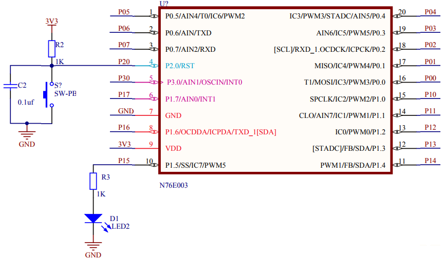
Schematic

Explanation
For demoing time-base generation, we don’t need any additional hardware since we will just be blinking P15 LED without software-based delays.
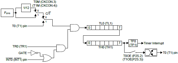
Before I start explaining the code example, I would like to discuss how Timer 0 and 1 works in Mode 1. In Mode 1, these timers behave like up-counting 16-bit timers. This means they can count (contents of TL and TH registers) from 0 to 65535 with every pulse/clock tick. There is no down-counting feature in these timers.
The source of these pulse/clock ticks can be from system clock, prescaled system clock or from external inputs. When external inputs are used, these timers can be used like counters. Unlike conventional 8051, there are options to take output from timers. The outputs change state with overflows/rollovers, i.e. when the timer counts resets from 65535 to 0.
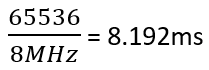
In the setup function, we do a couple of things. First, we setup the system clock source to 100kHz with HIRC as clock source. P15 is set as an output. Timer 0 is used and so there a 0 in timer setups. Timer 0 is clocked with system clock, i.e. 100kHz and so one tick is:
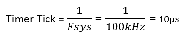
In Mode 1, the timer will reset/overflow after:
![]()
provided that the initial count of the timer was set to 0. This is what we are doing in the set up. After setting the timer’s count and the mode of operation, the timer is started.
disable_clock_source(ECLK);
set_clock_source(HIRC);
set_clock_division_factor(80);
P15_PushPull_Mode;
set_T0M;
TIMER0_MODE1_ENABLE;
set_Timer_0(0);
set_TR0;
Functions set_Timer_0 and get_Timer_0 writes Timer 0’s count and reads Timer 0’s count respectively.
void set_Timer_0(unsigned int value);
unsigned int get_Timer_0(void);
It is needed to toggle the state of the P15 LED and yeah, that is done at every half count of the timer, i.e. at every 327ms. In the main, the timer’s count is checked using get_Timer_0 function. When the timer’s count is less than 32767 counts, P15 LED is held high. P15 LED is set low when the timer’s count is greater than this 32767. In this way the toggling effect is achieved without software delays. However, the timer’s count is frequently polled.
if(get_Timer_0() < 32767)
{
P15 = 1;
}
else
{
P15 = 0;
}
Demo

Timer 1 – Stopwatch
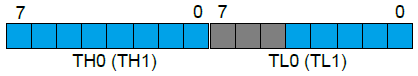
We have already seen the operation of general-purpose timers in Mode 1. In this segment, we will how to use these timers in Mode 0. Everything is same between Mode 0 and 1. However, the timer counts or resolutions vary in these modes. Mode 0 makes general purpose timers behave as 13-bit timer/counters.
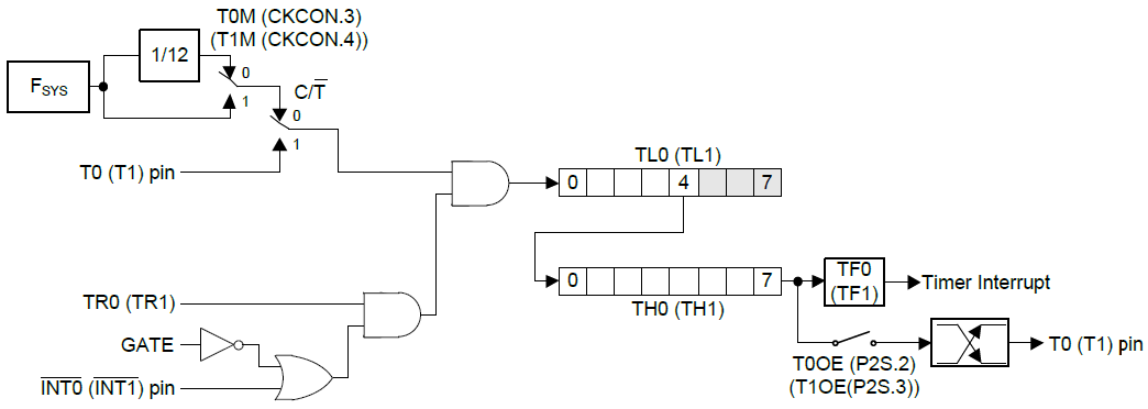
Check the block diagram shown above and compare with the one previously shown. Note the greyed-out part in this diagram. The upper bits of TL registers are not used in this mode. Between Mode 0 and 1, personally Mode 1 is easier than Mode 0.
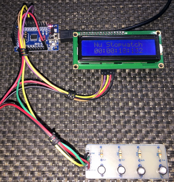
Here Timer 1 in Mode 0 is used to create a digital stopwatch.
Code
#include "N76E003_iar.h"
#include "SFR_Macro.h"
#include "Function_define.h"
#include "Common.h"
#include "Delay.h"
#include "LCD_3_Wire.h"
#define HIRC 0
#define LIRC 1
#define ECLK 2
unsigned char toggle = 0;
unsigned int ms = 0;
unsigned char sec = 0;
unsigned char min = 0;
unsigned char hrs = 0;
void setup(void);
void set_clock_source(unsigned char clock_source);
void disable_clock_source(unsigned char clock_source);
void set_clock_division_factor(unsigned char value);
void set_Timer_1_for_Mode_0(unsigned int value);
unsigned int get_Timer_1_for_Mode_0(void);
void print_C(unsigned char x_pos, unsigned char y_pos, unsigned char value);
void print_I(unsigned char x_pos, unsigned char y_pos, unsigned int value);
#pragma vector = 0x1B
__interrupt void Timer1_ISR (void)
{
set_Timer_1_for_Mode_0(0x1D64);
ms++;
if(ms == 499)
{
toggle = ~toggle;
}
if(ms > 999)
{
ms = 0;
sec++;
if(sec > 59)
{
sec = 0;
min++;
if(min > 59)
{
min = 0;
hrs++;
if(hrs > 23)
{
hrs = 0;
}
}
}
}
}
void main(void)
{
static char txt[] = {"Nu Stopwatch"};
setup();
LCD_goto(2, 0);
LCD_putstr(txt);
while(1)
{
if(P05 == 1)
{
set_ET1;
set_EA;
set_TR1;
set_Timer_1_for_Mode_0(0x1D64);
}
if(P06 == 1)
{
clr_ET1;
clr_EA;
clr_TR1;
toggle = 0;
}
if((P05 == 1) && (P06 == 1))
{
clr_ET1;
clr_EA;
clr_TR1;
ms = 0;
sec = 0;
min = 0;
hrs = 0;
toggle = 0;
set_Timer_1_for_Mode_0(0x1D64);
}
print_C(2, 1, hrs);
print_C(5, 1, min);
print_C(8, 1, sec);
print_I(11, 2, ms);
if(!toggle)
{
LCD_goto(4, 1);
LCD_putchar(':');
LCD_goto(7, 1);
LCD_putchar(':');
LCD_goto(10, 1);
LCD_putchar(':');
}
else
{
LCD_goto(4, 1);
LCD_putchar(' ');
LCD_goto(7, 1);
LCD_putchar(' ');
LCD_goto(10, 1);
LCD_putchar(' ');
}
};
}
void setup(void)
{
disable_clock_source(ECLK);
set_clock_source(HIRC);
set_clock_division_factor(1);
P05_Input_Mode;
P06_Input_Mode;
clr_T1M;
TIMER1_MODE0_ENABLE;
set_Timer_1_for_Mode_0(0x1D64);
LCD_init();
LCD_clear_home();
}
void set_clock_source(unsigned char clock_source)
{
switch(clock_source)
{
case LIRC:
{
set_OSC1;
clr_OSC0;
break;
}
case ECLK:
{
set_EXTEN1;
set_EXTEN0;
while((CKSWT & SET_BIT3) == 0);
clr_OSC1;
set_OSC0;
break;
}
default:
{
set_HIRCEN;
while((CKSWT & SET_BIT5) == 0);
clr_OSC1;
clr_OSC0;
break;
}
}
while((CKEN & SET_BIT0) == 1);
}
void disable_clock_source(unsigned char clock_source)
{
switch(clock_source)
{
case HIRC:
{
clr_HIRCEN;
break;
}
default:
{
clr_EXTEN1;
clr_EXTEN0;
break;
}
}
}
void set_clock_division_factor(unsigned char value)
{
CKDIV = value;
}
void set_Timer_1_for_Mode_0(unsigned int value)
{
TL1 = (value & 0x1F);
TH1 = ((value & 0xFFE0) >> 5);
}
unsigned int get_Timer_1_for_Mode_0(void)
{
unsigned char hb = 0x00;
unsigned char lb = 0x00;
unsigned int value = 0x0000;
value = TH1;
value <<= 8;
value |= TL1;
lb = (value & 0x001F);
hb = ((value & 0xFFE0) >> 5);
value = hb;
value <<= 8;
value |= lb;
return value;
}
void print_C(unsigned char x_pos, unsigned char y_pos, unsigned char value)
{
LCD_goto(x_pos, y_pos);
LCD_putchar((value / 10) + 0x30);
LCD_goto((x_pos + 1), y_pos);
LCD_putchar((value % 10) + 0x30);
}
void print_I(unsigned char x_pos, unsigned char y_pos, unsigned int value)
{
LCD_goto(x_pos, y_pos);
LCD_putchar((value / 100) + 0x30);
LCD_goto((x_pos + 1), y_pos);
LCD_putchar(((value % 100) / 10) + 0x30);
LCD_goto((x_pos + 2), y_pos);
LCD_putchar((value % 10) + 0x30);
}
Schematic
Explanation
Firstly, let us inspect the setup code:
disable_clock_source(ECLK);
set_clock_source(HIRC);
set_clock_division_factor(1);
P05_Input_Mode;
P06_Input_Mode;
clr_T1M;
TIMER1_MODE0_ENABLE;
set_Timer_1_for_Mode_0(0x1D64);
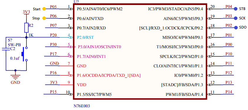
The system clock is set to 8MHz using HIRC. As per schematic and code, two buttons labelled Start and Stop are connected with P05 and P06 respectively. Timer 1 is set up in Mode 1 with prescaled system clock source (Fsys / 12). Thus, it has an input clock frequency of 666.67kHz. Thus, one timer tick is 1.5μs. To get the timer overflow and reset every 1 millisecond we will need:
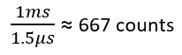
Since the timer is an up-counting timer and has a resolution of 13-bits, it will overflow after 8191 counts. Thus, to get 667 counts, we need to set is at:
![]()
The timer is, therefore, set at this count value.
Now how do we set the timer in Mode 1?
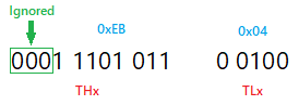
Check the register diagram below. The grey part is what is ignored. Remember that TL and TH are 16-bits as a whole but out of that we will just be using 13-bits.
In our case, the count 0x1D64 is segmented as the following in binary:
![]()
This number is masked as follows:
All of these is done by the following function:
void set_Timer_1_for_Mode_0(unsigned int value)
{
TL1 = (value & 0x1F);
TH1 = ((value & 0xFFE0) >> 5);
}
Reading the time is doing just the opposite of writing and this is accomplished by the following function:
unsigned int get_Timer_1_for_Mode_0(void)
{
unsigned char hb = 0x00;
unsigned char lb = 0x00;
unsigned int value = 0x0000;
value = TH1;
value <<= 8;
value |= TL1;
lb = (value & 0x001F);
hb = ((value & 0xFFE0) >> 5);
value = hb;
value <<= 8;
value |= lb;
return value;
}
Unlike the previous example, here interrupt is used to keep time. The timer run bit, global interrupt and Timer 1 interrupt are all enabled when the start button is pressed and are all disabled when the stop button is pressed or the stopwatch is reset by pressing both buttons.
if(P05 == 1)
{
set_ET1;
set_EA;
set_TR1;
set_Timer_1_for_Mode_0(0x1D64);
}
if(P06 == 1)
{
clr_ET1;
clr_EA;
clr_TR1;
toggle = 0;
}
if((P05 == 1) && (P06 == 1))
{
clr_ET1;
clr_EA;
clr_TR1;
ms = 0;
sec = 0;
min = 0;
hrs = 0;
toggle = 0;
set_Timer_1_for_Mode_0(0x1D64);
}
Inside the interrupt subroutine, the time keeping is done:
#pragma vector = 0x1B
__interrupt void Timer1_ISR (void)
{
set_Timer_1_for_Mode_0(0x1D64);
ms++;
if(ms == 499)
{
toggle = ~toggle;
}
if(ms > 999)
{
ms = 0;
sec++;
if(sec > 59)
{
sec = 0;
min++;
if(min > 59)
{
min = 0;
hrs++;
if(hrs > 23)
{
hrs = 0;
}
}
}
}
At every timer overflow interrupt the timer’s counter is reset to 0x1D64 to make sure that there are 667 counts before the overflow.
The time data is displayed on an LCD screen.
Demo
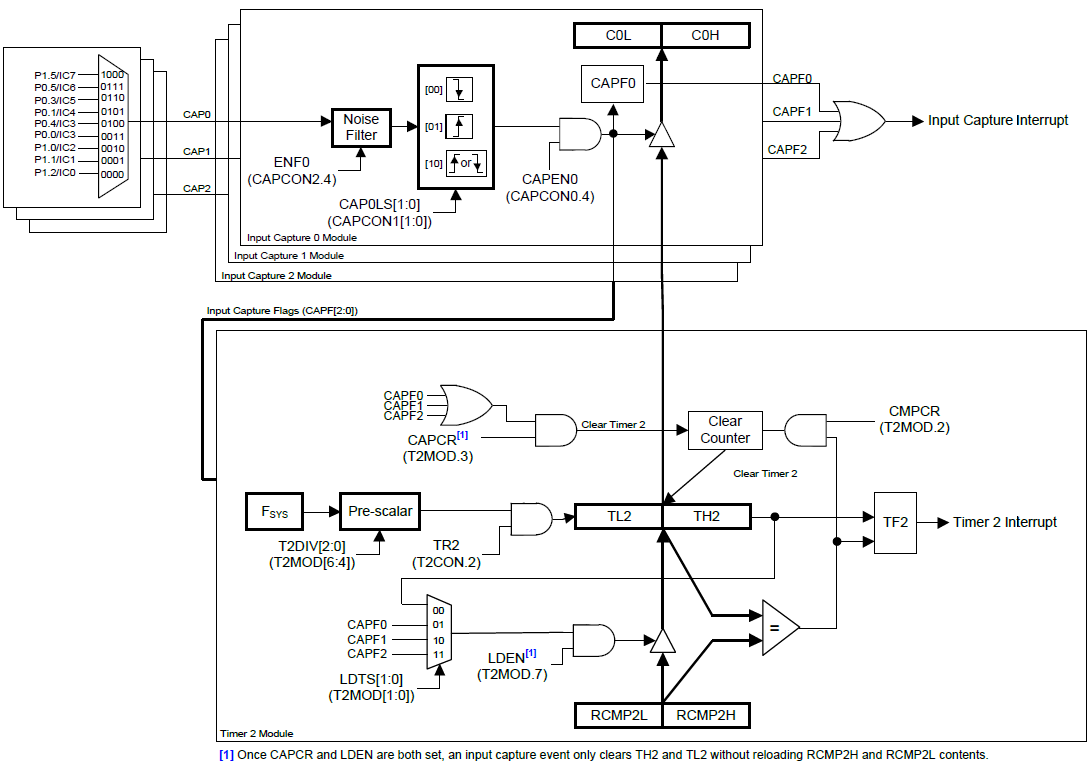
Timer 2 Input Capture – Frequency Counter
Timer 2, as I stated before, is different in many areas from the other timers of N76E003. In my opinion, it is best suited for measuring pulse widths, their periods and thereby frequencies. In other words, it is the best wave capturing tool that we have in N76E003s.
Unlike conventional 8051s, there varieties of option to capture wave or generate compare-match events.
In this segment, we will see how to make a frequency counter with Timer 2’s capture facility. We will also see how to generate Timer 1’s output.
Code
#include "N76E003_iar.h"
#include "SFR_Macro.h"
#include "Function_define.h"
#include "Common.h"
#include "Delay.h"
#include "LCD_3_Wire.h"
#define HIRC 0
#define LIRC 1
#define ECLK 2
#define timer_clock_speed 8000000.0
unsigned long overflow = 0;
unsigned long pulse_time = 0;
unsigned long start_time = 0;
unsigned long end_time = 0;
void setup(void);
void set_clock_source(unsigned char clock_source);
void disable_clock_source(unsigned char clock_source);
void set_clock_division_factor(unsigned char value);
void setup_GPIOs(void);
void setup_Timer_1(void);
void setup_Timer_2(void);
void setup_capture(void);
void set_Timer_1(unsigned int value);
void lcd_print(unsigned char x_pos, unsigned char y_pos, unsigned long value);
#pragma vector = 0x1B
__interrupt void Timer_1_ISR(void)
{
set_Timer_1(0);
}
#pragma vector = 0x2B
__interrupt void Timer_2_ISR(void)
{
clr_TF2;
overflow++;
}
#pragma vector = 0x63
__interrupt void Input_Capture_ISR(void)
{
if((CAPCON0 & SET_BIT0) != 0)
{
clr_CAPF0;
end_time = C0H;
end_time <<= 8;
end_time |= C0L;
pulse_time = ((overflow << 16) - start_time + end_time);
start_time = end_time;
overflow = 0;
}
}
void main(void)
{
register float f = 0.0;
setup();
LCD_init();
LCD_clear_home();
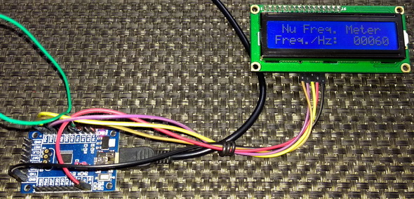
LCD_goto(1, 0);
LCD_putstr("Nu Freq. Meter");
LCD_goto(0, 1);
LCD_putstr("Freq./Hz:");
while(1)
{
f = (timer_clock_speed / ((float)pulse_time));
lcd_print(11, 1, ((unsigned long)f));
Timer0_Delay1ms(100);
};
}
void setup(void)
{
disable_clock_source(ECLK);
set_clock_source(HIRC);
set_clock_division_factor(1);
setup_GPIOs();
setup_capture();
setup_Timer_1();
setup_Timer_2();
set_EA;
}
void set_clock_source(unsigned char clock_source)
{
switch(clock_source)
{
case LIRC:
{
set_OSC1;
clr_OSC0;
break;
}
case ECLK:
{
set_EXTEN1;
set_EXTEN0;
while((CKSWT & SET_BIT3) == 0);
clr_OSC1;
set_OSC0;
break;
}
default:
{
set_HIRCEN;
while((CKSWT & SET_BIT5) == 0);
clr_OSC1;
clr_OSC0;
break;
}
}
while((CKEN & SET_BIT0) == 1);
}
void disable_clock_source(unsigned char clock_source)
{
switch(clock_source)
{
case HIRC:
{
clr_HIRCEN;
break;
}
default:
{
clr_EXTEN1;
clr_EXTEN0;
break;
}
}
}
void set_clock_division_factor(unsigned char value)
{
CKDIV = value;
}
void setup_GPIOs(void)
{
P00_PushPull_Mode;
P12_Input_Mode;
}
void setup_Timer_1(void)
{
set_T1M;
TIMER1_MODE1_ENABLE;
set_Timer_1(0);
P2S |= SET_BIT3;
set_TR1;
set_ET1;
}
void setup_Timer_2(void)
{
T2CON &= ~SET_BIT0;
T2MOD = 0x00;
set_TR2;
set_ET2;
}
void setup_capture(void)
{
IC0_P12_CAP0_FallingEdge_Capture;
set_ECAP;
}
void set_Timer_1(unsigned int value)
{
TH1 = ((value && 0xFF00) >> 8);
TL1 = (value & 0x00FF);
}
void lcd_print(unsigned char x_pos, unsigned char y_pos, unsigned long value)
{
LCD_goto(x_pos, y_pos);
LCD_putchar((value / 10000) + 0x30);
LCD_goto((x_pos + 1), y_pos);
LCD_putchar(((value % 10000) / 1000) + 0x30);
LCD_goto((x_pos + 2), y_pos);
LCD_putchar(((value % 1000) / 100) + 0x30);
LCD_goto((x_pos + 3), y_pos);
LCD_putchar(((value % 100) / 10) + 0x30);
LCD_goto((x_pos + 4), y_pos);
LCD_putchar((value % 10) + 0x30);
}
Schematic

Explanation
Before explaining the capture part, I would like to put emphasis on how to generate Timer 1’s output. The setup for timer is nothing different from other timer settings in Mode 1 except for the part shown below:
P2S |= SET_BIT3;
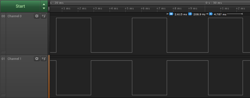
This code sets the timer output. Note that in this example, the system clock speed and hence the clock speed of all hardware sub-systems is set to 8MHz with HIRC and clock divider. Thus, Timer 1’s output will be high for:
and low for the same amount of time. So, the total time period of Timer 1’s output is roughly 16ms. Therefore, the frequency of this output is about 60Hz.
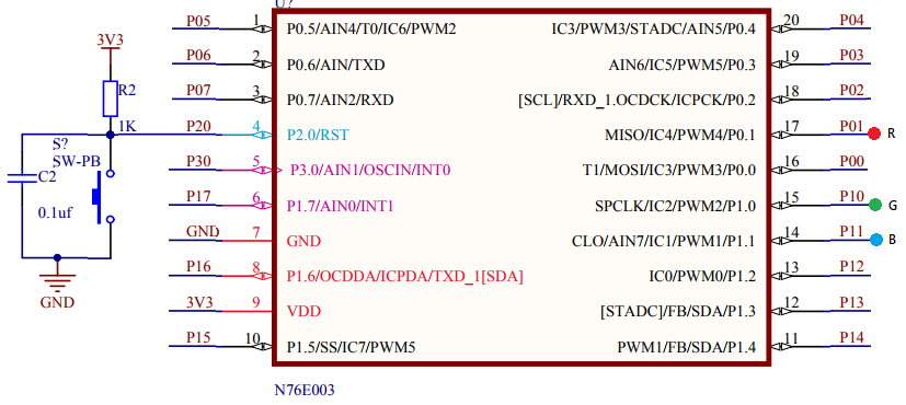
P00 is the Timer 1’s output pin and P12 is the capture pin of Timer 2. When P00 and P12 are shorted together, the frequency counter made here with Timer 2 and its capture unit will read 60Hz.
So how it is done by Timer 2 and the capture unit?
Here in this example, we don’t need the compare-match feature for the measurement of waveform timings and so all compare match features are disabled. We need to reload the timer when it overflows. Since the timer’s counter registers are not manipulated, they are set to zeros by default and so the reload count is zero. These are reflected by the first two lines of the timer’s setup:
void setup_Timer_2(void)
{
T2CON &= ~SET_BIT0;
T2MOD = 0x00;
set_TR2;
set_ET2;
}
Next, Timer 2 is started with its interrupt enabled.
Finally, the capture pin and its channel to be used are enabled using BSP-based definition. Capture interrupt is also enabled.
void setup_capture(void)
{
IC0_P12_CAP0_FallingEdge_Capture;
set_ECAP;
}
Note that this is the confusing part of the code. There are three capture channels (CAP0, CAP1 and CAP2). These channels share 9 input capture GPIO pins. The pins are cleverly multiplexed. Detection edge selections can be also done. The BSP definition-names state these parameters. For example, the definition used here means:
“input capture pin 0 connected to P12 GPIO pin is connected to capture channel 0 to detect falling edge transitions”.
Once the hardware setup is complete, the game now resides in the capture interrupt part:
#pragma vector = 0x63
__interrupt void Input_Capture_ISR(void)
{
if((CAPCON0 & SET_BIT0) != 0)
{
clr_CAPF0;
end_time = C0H;
end_time <<= 8;
end_time |= C0L;
pulse_time = ((overflow << 16) - start_time + end_time);
start_time = end_time;
overflow = 0;
}
}
Since there is one interrupt vector for all three capture channels, we have check first which capture channel caused the interrupt and clear that particular interrupt flag soon. Capture interrupt, in this case, occurs when a falling edge is detected by CAP0 channel. When such an interrupt occurs, the time of its happening, i.e. the counter value of Timer 2 at that instance is stored. This marks the first falling edge event. To measure period or frequency of a waveform, another such falling edge is needed. Therefore, when another falling edge is detected by the capture hardware, the process repeats. This results in the time capture of two events.
We know the frequency of the timer’s clock and so we can find the value of its each tick. We have two captures in form of two Timer 2 counts. We can find the difference between them and thereby compute the time period (pulse_time).
Since the time period of the captured waveform is calculated, its frequency can be deduced. This is done in the main loop.
f = (timer_clock_speed / ((float)pulse_time));
Demo
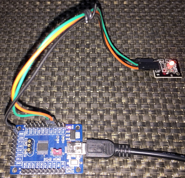
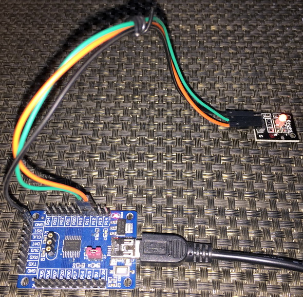
Timer 2 Pulse Width Capture – Interfacing HC-SR04 SONAR
In the last segment, it was demonstrated how to capture a waveform and compute its frequency using Timer 2’s capture hardware. This segment is basically an extension of the last segment. Here, it will be shown how we can use two capture channels connected to the same capture pin to find out the pulse width of a pulse. For demoing this idea, a HC-SR04 ultrasonic SONAR sensor is used. The SONAR sensor gives a pulse output that varies in width according to the distance between the sensor and a target.
Code
#include "N76E003.h"
#include "SFR_Macro.h"
#include "Function_define.h"
#include "Common.h"
#include "Delay.h"
#include "LCD_3_Wire.h"
#define HIRC 0
#define LIRC 1
#define ECLK 2
unsigned int pulse_width = 0;
void setup(void);
void set_clock_source(unsigned char clock_source);
void disable_clock_source(unsigned char clock_source);
void set_system_clock_frequency(unsigned long F_osc, unsigned long F_sys);
void setup_GPIOs(void);
void setup_Timer_2(void);
void setup_capture(void);
void set_Timer_2(unsigned int value);
void set_Timer_2_reload_compare(unsigned int value);
void lcd_print(unsigned char x_pos, unsigned char y_pos, unsigned int value);
void Input_Capture_ISR(void)
interrupt 12
{
if(CAPCON0 & 0x01)
{
clr_CAPF0;
}
if(CAPCON0 & 0x02)
{
clr_CAPF1;
pulse_width = C1H;
pulse_width <<= 8;
pulse_width |= C1L;
}
}
void main(void)
{
unsigned int range = 0;
LCD_init();
LCD_clear_home();
LCD_goto(0, 0);
LCD_putstr("Pamge/cm:");
LCD_goto(0, 1);
LCD_putstr("Pulse/us:");
setup();
while(1)
{
set_P11;
Timer3_Delay10us(1);
clr_P11;
range = ((unsigned int)(((float)pulse_width) / 58.0));
lcd_print(11, 0, range);
lcd_print(11, 1, pulse_width);
Timer0_Delay1ms(900);
};
}
void setup(void)
{
disable_clock_source(ECLK);
set_clock_source(HIRC);
set_system_clock_frequency(16, 16);
setup_GPIOs();
setup_capture();
setup_Timer_2();
set_EA;
}
void set_clock_source(unsigned char clock_source)
{
switch(clock_source)
{
case LIRC:
{
set_OSC1;
clr_OSC0;
break;
}
case ECLK:
{
set_EXTEN1;
set_EXTEN0;
while((CKSWT & SET_BIT3) == 0);
clr_OSC1;
set_OSC0;
break;
}
default:
{
set_HIRCEN;
while((CKSWT & SET_BIT5) == 0);
clr_OSC1;
clr_OSC0;
break;
}
}
while((CKEN & SET_BIT0) == 1);
}
void disable_clock_source(unsigned char clock_source)
{
switch(clock_source)
{
case HIRC:
{
clr_HIRCEN;
break;
}
default:
{
clr_EXTEN1;
clr_EXTEN0;
break;
}
}
}
void set_system_clock_frequency(unsigned long F_osc, unsigned long F_sys)
{
F_osc = (F_osc / (0x02 * F_sys));
if((F_osc >= 0x00) && (F_osc <= 0xFF))
{
CKDIV = ((unsigned char)F_osc);
}
}
void setup_GPIOs(void)
{
P11_PushPull_Mode;
P12_Input_Mode;
}
void setup_Timer_2(void)
{
set_Timer_2_reload_compare(0);
set_Timer_2(0);
set_LDEN;
T2MOD |= 0x01;
T2MOD |= 0x20;
set_TR2;
}
void setup_capture(void)
{
CAPCON0 = 0x30;
CAPCON1 = 0x01;
CAPCON2 = 0x30;
CAPCON3 = 0x00;
CAPCON4 = 0x00;
set_ECAP;
}
void set_Timer_2(unsigned int value)
{
TL2 = (value & 0x00FF);
TH2 = ((value & 0xFF00) >> 0x08);
}
void set_Timer_2_reload_compare(unsigned int value)
{
RCMP2L = (value & 0x00FF);
RCMP2H = ((value & 0xFF00) >> 0x08);
}
void lcd_print(unsigned char x_pos, unsigned char y_pos, unsigned int value)
{
LCD_goto(x_pos, y_pos);
LCD_putchar((value / 10000) + 0x30);
LCD_goto((x_pos + 1), y_pos);
LCD_putchar(((value % 10000) / 1000) + 0x30);
LCD_goto((x_pos + 2), y_pos);
LCD_putchar(((value % 1000) / 100) + 0x30);
LCD_goto((x_pos + 3), y_pos);
LCD_putchar(((value % 100) / 10) + 0x30);
LCD_goto((x_pos + 4), y_pos);
LCD_putchar((value % 10) + 0x30);
}
Schematic

Explanation
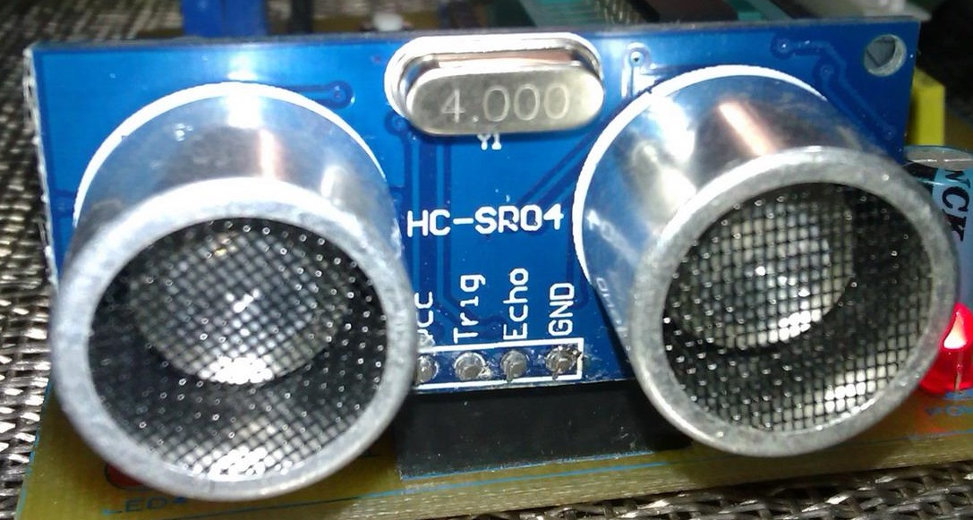
HC-SR04 SONAR sensor has two pins apart from power supply pins. These pins are labelled “Echo” and “Trigger”. When the trigger pin of a HC-SR04 is set high for about 10μs, it acknowledges this short duration pulse in the trigger pin as a command from its host micro to measure and return distance data.

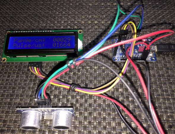
P11 is setup as the trigger pin and P12 is set up as the echo pin. The concepts of input capture are same as in the last capture example but there are a few minor changes. Firstly, the system clock speed is set to full 16MHz using HIRC. Secondly, the setup of Timer 2 is slightly changed. Auto-reloading is enabled this time. Timer 2’s clock is prescaled to 1MHz. This is done so in order to make sure that the capture has a resolution of 1μs and the timer doesn’t overflow while taking measurements. The maximum possible width of a pulse from HC-SR04 is 38ms when no obstacle is detected by it but with this timer setup we can measure pulse widths up to 65ms. Timer 2 is also set up as to reset its count when a CAP0 event occurs.
void setup_Timer_2(void)
{
set_Timer_2_reload_compare(0);
set_Timer_2(0);
set_LDEN;
T2MOD |= 0x01;
T2MOD |= 0x20;
set_TR2;
}
In order to measure pulse widths, we can use one capture channel in both edge capture mode or use two capture channels connected to the same input capture GPIO pin detecting different edges. The latter is used here.
void setup_capture(void)
{
CAPCON0 = 0x30;
CAPCON1 = 0x01;
CAPCON2 = 0x30;
CAPCON3 = 0x00;
CAPCON4 = 0x00;
set_ECAP;
}
I didn’t use BSP-based definitions for setting up captures in this example because of some limitation. BSP-based definitions reset selections. This is why I configured the input capture control registers manually. Two capture channels having different edge detections are used and both of these channels share P12 or IC0 pin.
Now when HC-SR04 is triggered, it will give out a pulse. We have to measure the width of that pulse. A pulse is defined by a rising edge and a falling edge. CAP0 channel is set to detect the rising edge of the pulse and reset Timer 2 to 0 count. CAP1 channel is used to detect the falling edge of the same pulse and read Timer 2’s count. This count represents pulse width in microseconds.
void Input_Capture_ISR(void)
interrupt 12
{
if(CAPCON0 & 0x01)
{
clr_CAPF0;
}
if(CAPCON0 & 0x02)
{
clr_CAPF1;
pulse_width = C1H;
pulse_width <<= 8;
pulse_width |= C1L;
}
}
In the main loop, distance is calculated using this measured pulse width time and the formula given in HC-SR04’s datasheet.
range = ((unsigned int)(((float)pulse_width) / 58.0));
The distance found between an object and HC-SR04 is displayed on a text LCD.
Demo
Timer 3 – Driving 7 Segments, LED and Scanning Keypad
We all know that N76E003 is a cool chip but it lacks GPIOs unlike other chips of similar capabilities. Thus, we must be miser while using GPIOs. When it is needed to interface several inputs and outputs with a microcontroller using fewer pins, we often take the assistance of logic ICs like shift registers, counters, multiplexers, etc. We have already used this technique while making the 3-wire LCD interface. An LCD has its own controller(s) to take care of projecting data on the screen once data has been feed to it. However, that’s not the case with seven segment displays and keypads when used without any specialized driver IC like TM1640/MAX7219. It is, then, a job for a host micro to do the scanning and data manipulation periodically with affecting other tasks. This can be achieved easily with a timer.
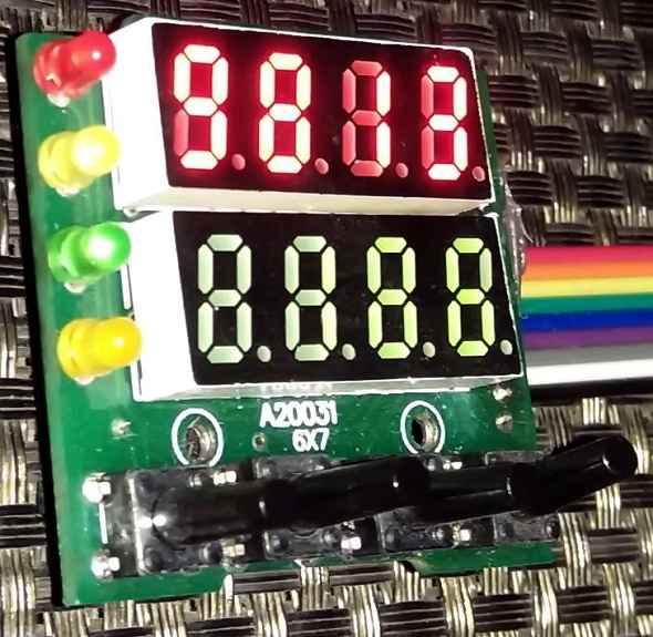
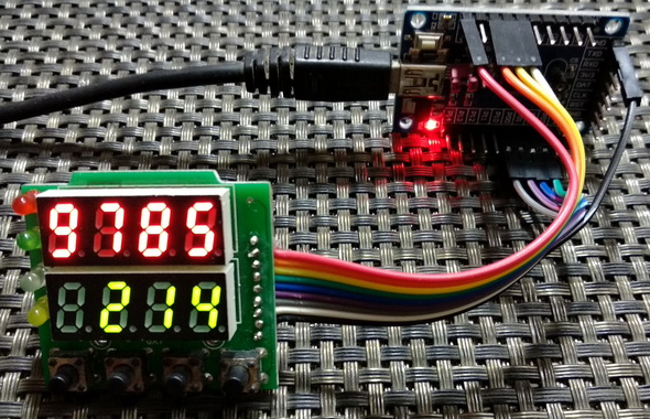
In this segment, we will see how the aforementioned is done with Timer 3. For the demo, I used a salvaged temperature controller’s I/O unit. The I/O unit consists of two 4-digit seven segment displays, four LEDs and four push buttons. It is made with a 74HC164 Serial-In-Parallel-Out (SPIO) shift register and a 74HC145 BCD-to-Decimal decoder. In order to use it in real-time, its displays, LEDs and buttons should be scanned and updated at a fast rate without hindering any part of an application running in main loop.
Code
#include "N76E003_iar.h"
#include "SFR_Macro.h"
#include "Function_define.h"
#include "Common.h"
#include "Delay.h"
#define HIRC 0
#define LIRC 1
#define ECLK 2
#define GATE_HIGH set_P15
#define GATE_LOW clr_P15
#define CLK_HIGH set_P16
#define CLK_LOW clr_P16
#define A_HIGH set_P00
#define A_LOW clr_P00
#define B_HIGH set_P01
#define B_LOW clr_P01
#define C_HIGH set_P02
#define C_LOW clr_P02
#define D_HIGH set_P03
#define D_LOW clr_P03
#define SW P17
#define top_seg 4
#define bot_seg 0
#define HIGH 1
#define LOW 0
const unsigned char num[0x0A] = {0xED, 0x21, 0x8F, 0xAB, 0x63, 0xEA, 0xEE, 0xA1, 0xEF, 0xEB};
unsigned char data_values[0x09] = {0x00, 0x00, 0x00, 0x00, 0x00, 0x00, 0x00, 0x00, 0x00};
unsigned char SW_in = 0;
unsigned char n = 0;
void setup(void);
void setup_GPIOs(void);
void setup_Timer_3(void);
void set_Timer_3(unsigned int value);
unsigned int get_Timer_3(void);
void write_74HC164(register unsigned char value);
void write_74HC145(register unsigned char channel);
void show_LEDs(unsigned char LED1_state, unsigned char LED2_state, unsigned char LED3_state, unsigned char LED4_state);
void show_numbers(signed int value, unsigned char pos);
#pragma vector = 0x83
__interrupt void Timer3_ISR(void)
{
write_74HC164(data_values[n]);
write_74HC145(n);
n++;
if(n > 9)
{
n = 0;
}
clr_TF3;
}
void main (void)
{
unsigned int i = 0;
unsigned int j = 9999;
setup();
while(1)
{
switch(SW_in)
{
case 1:
{
show_LEDs(1, 0, 0, 0);
break;
}
case 2:
{
show_LEDs(0, 1, 0, 0);
break;
}
case 3:
{
show_LEDs(0, 0, 1, 0);
break;
}
case 4:
{
show_LEDs(0, 0, 0, 1);
break;
}
}
SW_in = 0x00;
i++;
j--;
if(i > 9999)
{
i = 0;
j = 9999;
}
show_numbers(i, bot_seg);
show_numbers(j, top_seg);
Timer1_Delay10ms(40);
show_LEDs(0, 0, 0, 0);
};
}
void setup(void)
{
setup_GPIOs();
setup_Timer_3();
}
void setup_GPIOs(void)
{
P00_PushPull_Mode;
P01_PushPull_Mode;
P02_PushPull_Mode;
P03_PushPull_Mode;
P15_PushPull_Mode;
P16_PushPull_Mode;
P17_Input_Mode;
}
void setup_Timer_3(void)
{
set_Timer_3(0xF9C0);
set_ET3;
set_EA;
set_TR3;
}
void set_Timer_3(unsigned int value)
{
RL3 = (value & 0x00FF);
RH3 = ((value && 0xFF00) >> 8);
}
unsigned int get_Timer_3(void)
{
unsigned int value = 0x0000;
value = RH3;
value <<= 8;
value |= RL3;
return value;
}
void write_74HC164(register unsigned char value)
{
register unsigned char s = 0x08;
while(s > 0)
{
if((value & 0x80) != 0x00)
{
GATE_HIGH;
}
else
{
GATE_LOW;
}
CLK_HIGH;
CLK_LOW;
value <<= 1;
s--;
};
}
void write_74HC145(register unsigned char channel)
{
P0 = 0x00;
switch(channel)
{
case 0:
{
asm("nop");
if(SW == LOW)
{
SW_in = 1;
}
break;
}
case 1:
{
P0 = 0x01;
break;
}
case 2:
{
P0 = 0x02;
break;
}
case 3:
{
P0 = 0x03;
break;
}
case 4:
{
P0 = 0x04;
break;
}
case 5:
{
P0 = 0x05;
break;
}
case 6:
{
P0 = 0x06;
break;
}
case 7:
{
P0 = 0x07;
asm("nop");
if(SW == LOW)
{
SW_in = 2;
}
break;
}
case 8:
{
P0 = 0x08;
asm("nop");
if(SW == LOW)
{
SW_in = 3;
}
break;
}
case 9:
{
P0 = 0x09;
asm("nop");
if(SW == LOW)
{
SW_in = 4;
}
break;
}
}
}
void show_LEDs(unsigned char LED1_state, unsigned char LED2_state, unsigned char LED3_state, unsigned char LED4_state)
{
switch(LED1_state)
{
case HIGH:
{
data_values[8] |= 0x80;
break;
}
case LOW:
{
data_values[8] &= 0x7F;
break;
}
}
switch(LED2_state)
{
case HIGH:
{
data_values[8] |= 0x40;
break;
}
case LOW:
{
data_values[8] &= 0xBF;
break;
}
}
switch(LED3_state)
{
case HIGH:
{
data_values[8] |= 0x08;
break;
}
case LOW:
{
data_values[8] &= 0xF7;
break;
}
}
switch(LED4_state)
{
case HIGH:
{
data_values[8] |= 0x02;
break;
}
case LOW:
{
data_values[8] &= 0xFD;
break;
}
}
}
void show_numbers(signed int value, unsigned char pos)
{
register unsigned char ch = 0x00;
if((value >= 0) && (value <= 9))
{
ch = (value % 10);
data_values[(0 + pos)] = num[ch];
data_values[(1 + pos)] = 0x00;
data_values[(2 + pos)] = 0x00;
data_values[(3 + pos)] = 0x00;
}
else if((value > 9) && (value <= 99))
{
ch = (value % 10);
data_values[(0 + pos)] = num[ch];
ch = ((value / 10) % 10);
data_values[(1 + pos)] = num[ch];
data_values[(2 + pos)] = 0x00;
data_values[(3 + pos)] = 0x00;
}
else if((value > 99) && (value <= 999))
{
ch = (value % 10);
data_values[(0 + pos)] = num[ch];
ch = ((value / 10) % 10);
data_values[(1 + pos)] = num[ch];
ch = ((value / 100) % 10);
data_values[(2 + pos)] = num[ch];
data_values[(3 + pos)] = 0x00;
}
else if((value > 999) && (value <= 9999))
{
ch = (value % 10);
data_values[(0 + pos)] = num[ch];
ch = ((value / 10) % 10);
data_values[(1 + pos)] = num[ch];
ch = ((value / 100) % 10);
data_values[(2 + pos)] = num[ch];
ch = (value / 1000);
data_values[(3 + pos)] = num[ch];
}
}
Schematic


Explanation
Timer 3’s internal hardware is very simple. It is an up-counting timer and is run by using system clock as clock source. There is a prescalar to reduce the system clock input. The main feature of Timer 3 is it auto-reload feature. This feature basically allows us to forget reloading its 16-bit counter unlike Timer 0 and 1. There no external input or output option for this timer. Owing to all these, it is most suitable for time-base generation and serial communication.
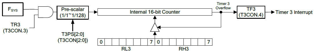
In this demo, Timer 3 is set to interrupt every 100μs.

The following code sets up Timer 3 as discussed:
void setup_Timer_3(void)
{
set_Timer_3(0xF9C0);
set_ET3;
set_EA;
set_TR3;
}
Note that Timer 3’s input clock and system clock frequency is 16MHz since no prescalar is used.
Now what we are doing inside the timer interrupt? According to the schematic and objective of this project, we need to update the seven segment displays and read the 4-bit keypad so fast that it looks as if everything is being done without any delay and in real time.
#pragma vector = 0x83
__interrupt void Timer3_ISR(void)
{
write_74HC164(data_values[n]);
write_74HC145(n);
n++;
if(n > 9)
{
n = 0;
}
clr_TF3;
}
Inside timer ISR, both logic ICs are updated. Firstly, the number to be displayed is sent to the 74HC164 IC and then the seven-segment display to show the number is updated by writing the 74HC145 IC. At every interrupt, one seven segment display is updated. There are 8 such displays and so it takes less than a millisecond to update all these displays. Everything seems to complete in the blink of an eye. During this time the keypad is also scanned in the main. With different keys, different LEDs light up.
Demo
Simple PWM – RGB LED Fading
PWM hardware is another basic requirement for any modern-era microcontroller. We can use PWM for a number of applications like motor control, light control, switch-mode power supplies (SMPSs), etc. With PWM we can also simulate digital-to-analogue converter (DAC). Fortunately, N76E003 comes with a separate PWM block that is not a part of any internal timer. It has all the feature that you can imagine. It can be used to generate simple independent 6 single channel PWMs. It can also be used to generate complementary and interdependent PWMs with dead time feature.
Code
#include "N76E003.h"
#include "SFR_Macro.h"
#include "Function_define.h"
#include "Common.h"
#include "Delay.h"
#include "soft_delay.h"
unsigned int R_value[10] = {20, 150, 250, 360, 440, 560, 680, 820, 900, 1020};
unsigned int G_value[10] = {440, 560, 680, 820, 900, 1020, 20, 150, 250, 360};
unsigned int B_value[10] = {900, 1020, 20, 150, 250, 360, 440, 560, 680, 820};
void set_PWM_period(unsigned int value);
void set_PWM0(unsigned int value);
void set_PWM1(unsigned int value);
void set_PWM2(unsigned int value);
void set_PWM3(unsigned int value);
void set_PWM4(unsigned int value);
void set_PWM5(unsigned int value);
void main(void)
{
signed int i = 0;
signed char j = 0;
P01_PushPull_Mode;
P10_PushPull_Mode;
P11_PushPull_Mode;
PWM1_P11_OUTPUT_ENABLE;
PWM2_P10_OUTPUT_ENABLE;
PWM4_P01_OUTPUT_ENABLE;
PWM_IMDEPENDENT_MODE;
PWM_EDGE_TYPE;
set_CLRPWM;
PWM_CLOCK_FSYS;
PWM_CLOCK_DIV_64;
PWM_OUTPUT_ALL_NORMAL;
set_PWM_period(1023);
set_PWMRUN;
while(1)
{
for(i = 0; i < 1024; i += 10)
{
set_PWM1(i);
delay_ms(20);
}
for(i = 1023; i > 0; i -= 10)
{
set_PWM1(i);
delay_ms(20);
}
for(i = 0; i < 1024; i += 10)
{
set_PWM2(i);
delay_ms(20);
}
for(i = 1023; i > 0; i -= 10)
{
set_PWM2(i);
delay_ms(20);
}
for(i = 0; i < 1024; i += 10)
{
set_PWM4(i);
delay_ms(20);
}
for(i = 1023; i > 0; i -= 10)
{
set_PWM4(i);
delay_ms(20);
}
delay_ms(600);
for(i = 0; i <=9; i++)
{
for(j = 0; j <= 9; j++)
{
set_PWM4(R_value[j]);
set_PWM1(G_value[j]);
set_PWM2(B_value[j]);
delay_ms(200);
}
for(j = 9; j >= 0; j--)
{
set_PWM4(R_value[j]);
set_PWM1(G_value[j]);
set_PWM2(B_value[j]);
delay_ms(200);
}
}
delay_ms(600);
}
}
void set_PWM_period(unsigned int value)
{
PWMPL = (value & 0x00FF);
PWMPH = ((value & 0xFF00) >> 8);
}
void set_PWM0(unsigned int value)
{
PWM0L = (value & 0x00FF);
PWM0H = ((value & 0xFF00) >> 8);
set_LOAD;
}
void set_PWM1(unsigned int value)
{
PWM1L = (value & 0x00FF);
PWM1H = ((value & 0xFF00) >> 8);
set_LOAD;
}
void set_PWM2(unsigned int value)
{
PWM2L = (value & 0x00FF);
PWM2H = ((value & 0xFF00) >> 8);
set_LOAD;
}
void set_PWM3(unsigned int value)
{
PWM3L = (value & 0x00FF);
PWM3H = ((value & 0xFF00) >> 8);
set_LOAD;
}
void set_PWM4(unsigned int value)
{
set_SFRPAGE;
PWM4L = (value & 0x00FF);
PWM4H = ((value & 0xFF00) >> 8);
clr_SFRPAGE;
set_LOAD;
}
void set_PWM5(unsigned int value)
{
set_SFRPAGE;
PWM5L = (value & 0x00FF);
PWM5H = ((value & 0xFF00) >> 8);
clr_SFRPAGE;
set_LOAD;
}
Schematic
Explanation
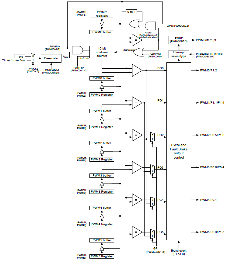
PWM generated by the N76E003’s PWM hardware is based on compare-match principle and this is evident from its block diagram. There are 6 PWM channels and they can be used independently or as interdependent groups to form complimentary PWMs. PWMs generated by N76E003 can be edge-aligned or centre-aligned PWMs as per user’s requirement. The PWM block can be clocked directly by the system clock or by Timer 1 overflow. Additionally, there is a prescalar unit to reduce input clock source.
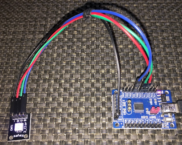
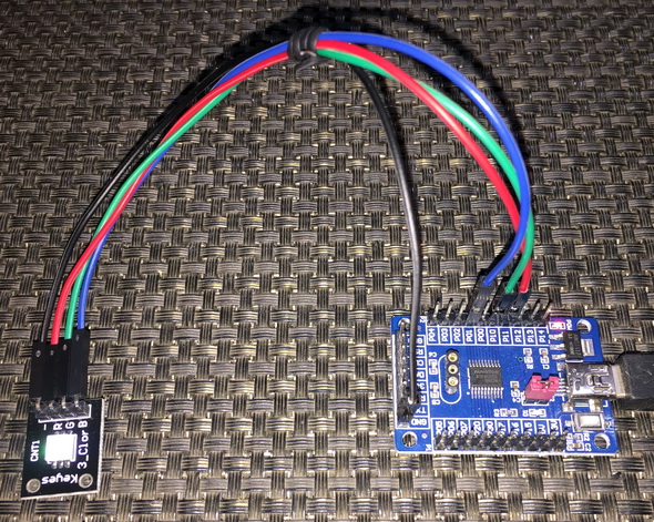
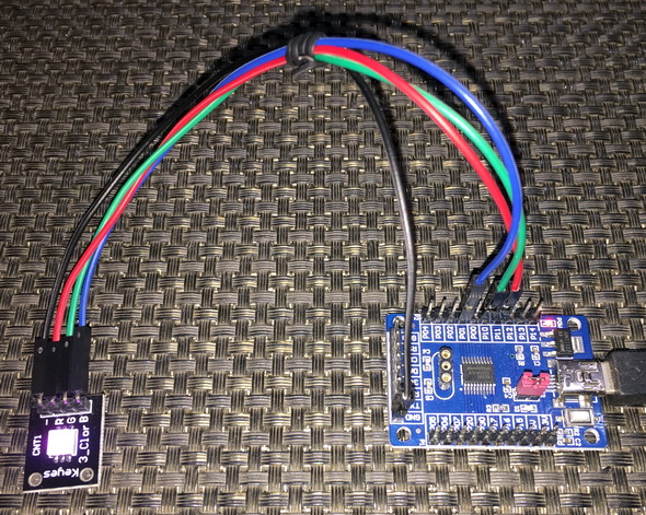
For demonstrating N76E003’s PWM feature, I used an RGB LED. Three independent PWMs were generated using PWM channels 1,2 and 4. Let us look into the process of setting up the PWM channels and the PWM hardware. We must firstly set the PWM GPIOs as push-pull GPIOs since PWM is an output function of GPIO pins. We must also enable the PWM output channels we want to use.
P01_PushPull_Mode;
P10_PushPull_Mode;
P11_PushPull_Mode;
PWM1_P11_OUTPUT_ENABLE;
PWM2_P10_OUTPUT_ENABLE;
PWM4_P01_OUTPUT_ENABLE;
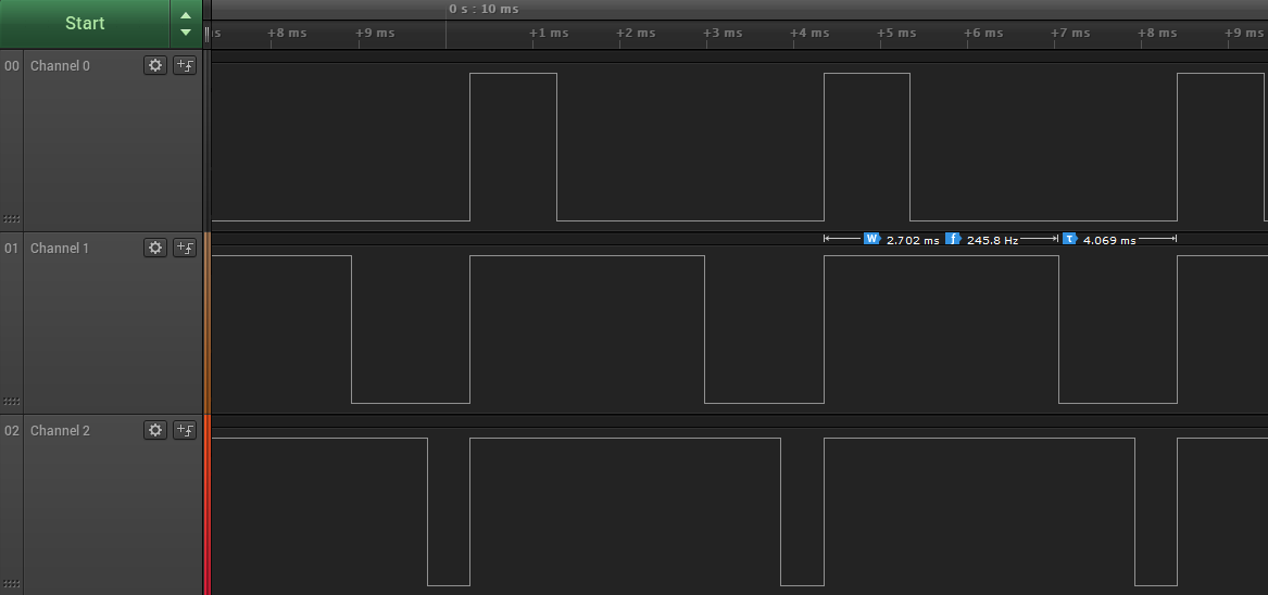
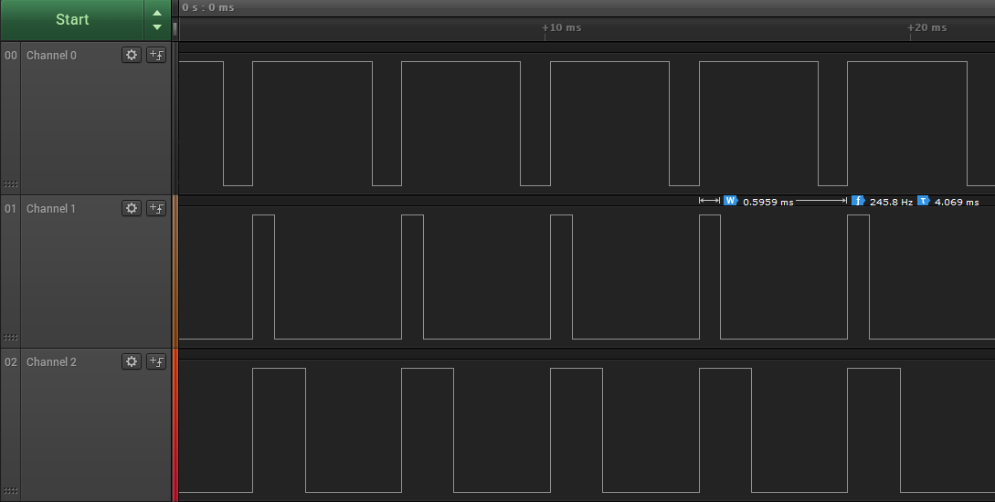
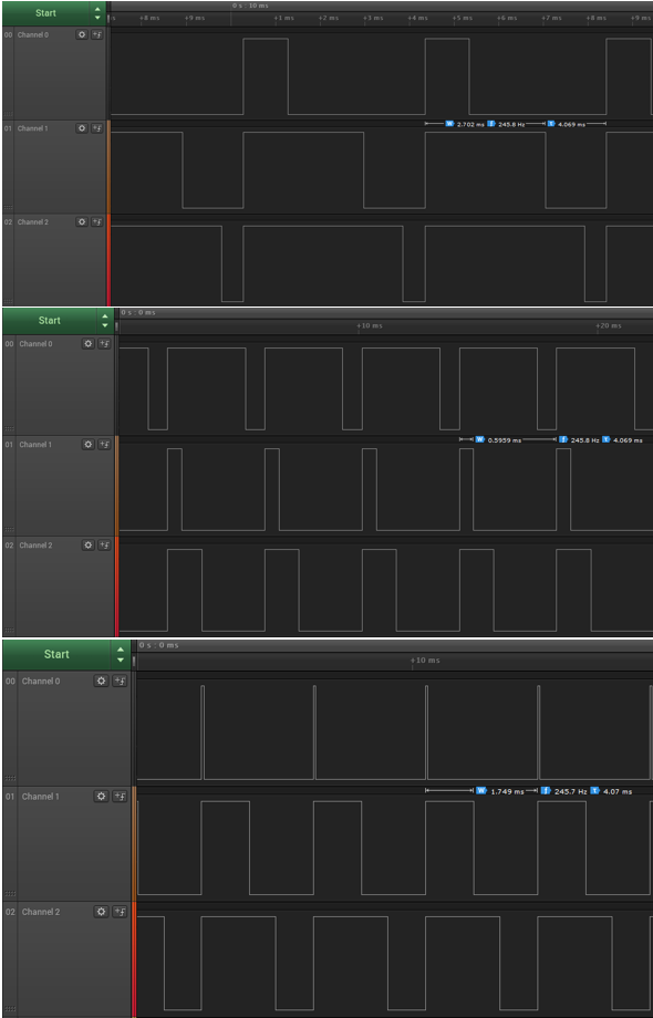
Secondly, the PWM hardware is set up according to our needs. Since we need independent PWMs here, independent PWM mode is selected. Edge-align PWM is selected since it is most easy to understand and use. The PWM channels are reset before using them. The PWM outputs are non-inverted and so they are characterized as normal PWMs. Here, I use system clock as the clock source for the PWM block but it is prescaled/divided by 64 to get an effective PWM clock of 250kHz. The PWM resolution is set to 10-bits when we set the period count or maximum PWM value/duty cycle. Setting the period count yields in setting up the internal PWM counter. This gives a PWM of approximately 245Hz frequency or 4ms period. Finally, the PWM hardware is enabled after setting up all these.
PWM_IMDEPENDENT_MODE;
PWM_EDGE_TYPE;
set_CLRPWM;
PWM_CLOCK_FSYS;
PWM_CLOCK_DIV_64;
PWM_OUTPUT_ALL_NORMAL;
set_PWM_period(1023);
set_PWMRUN;

To change PWM duty cycle, functions like the one shown below is called. After altering the duty cycle or compare value, the new value is loaded and run.
void set_PWMn(unsigned int value)
{
PWMnL = (value & 0x00FF);
PWMnH = ((value & 0xFF00) >> 8);
set_LOAD;
}
In the demo, the RGB LED fades different colours as a symbol of changing PWMs.
Demo
Complementary PWM with Dead Time
In the last section, we saw how we can generate independent PWM. Now we will see complimentary or group PWM with dead-time. We will also see the things that were skipped in the previous segment.
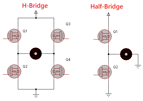
Complementary PWM with dead-time feature is a must-have feature of any PWM drives in today’s embedded-system industry. Unlike the simple PWM we saw previously, this kind of PWM has most usage. Complementary PWM with dead-time is used in applications where we need to design motor controllers, SMPSs, inverters, etc with H-bridges or half-bridges. In such applications, PWMs need to operate in groups while ensuring that both PWMs don’t turn on at the same time. One PWM in a group should be the opposite/antiphase of the other in terms of duty-cycle or waveshape.
Code
#include "N76E003.h"
#include "SFR_Macro.h"
#include "Function_define.h"
#include "Common.h"
#include "Delay.h"
void set_PWM_period(unsigned int value);
void set_PWM0(unsigned int value);
void set_PWM1(unsigned int value);
void set_PWM2(unsigned int value);
void set_PWM3(unsigned int value);
void set_PWM4(unsigned int value);
void set_PWM5(unsigned int value);
void set_PWM_dead_time(unsigned int value);
void main(void)
{
signed int i = 0;
P11_PushPull_Mode;
P12_PushPull_Mode;
PWM0_P12_OUTPUT_ENABLE;
PWM1_P11_OUTPUT_ENABLE;
PWM_COMPLEMENTARY_MODE;
PWM_CENTER_TYPE;
set_CLRPWM;
PWM_CLOCK_FSYS;
PWM_CLOCK_DIV_64;
PWM0_OUTPUT_INVERSE;
PWM1_OUTPUT_INVERSE;
set_PWM_period(600);
set_PWM_dead_time(40);
PWM01_DEADTIME_ENABLE;
set_PWMRUN;
while(1)
{
for(i = 0; i < 600; i++)
{
set_PWM0(i);
Timer0_Delay1ms(5);
}
for(i = 600; i > 0; i--)
{
set_PWM0(i);
Timer0_Delay1ms(5);
}
};
}
void set_PWM_period(unsigned int value)
{
PWMPL = (value & 0x00FF);
PWMPH = ((value & 0xFF00) >> 8);
}
void set_PWM0(unsigned int value)
{
PWM0L = (value & 0x00FF);
PWM0H = ((value & 0xFF00) >> 8);
set_LOAD;
}
void set_PWM1(unsigned int value)
{
PWM1L = (value & 0x00FF);
PWM1H = ((value & 0xFF00) >> 8);
set_LOAD;
}
void set_PWM2(unsigned int value)
{
PWM2L = (value & 0x00FF);
PWM2H = ((value & 0xFF00) >> 8);
set_LOAD;
}
void set_PWM3(unsigned int value)
{
PWM3L = (value & 0x00FF);
PWM3H = ((value & 0xFF00) >> 8);
set_LOAD;
}
void set_PWM4(unsigned int value)
{
set_SFRPAGE;
PWM4L = (value & 0x00FF);
PWM4H = ((value & 0xFF00) >> 8);
clr_SFRPAGE;
set_LOAD;
}
void set_PWM5(unsigned int value)
{
set_SFRPAGE;
PWM5L = (value & 0x00FF);
PWM5H = ((value & 0xFF00) >> 8);
clr_SFRPAGE;
set_LOAD;
}
void set_PWM_dead_time(unsigned int value)
{
unsigned char hb = 0;
unsigned char lb = 0;
lb = (value & 0x00FF);
hb = ((value & 0x0100) >> 8);
BIT_TMP = EA;
EA = 0;
TA = 0xAA;
TA = 0x55;
PDTEN &= 0xEF;
PDTEN |= hb;
PDTCNT = lb;
EA = BIT_TMP;
}
Schematic
Explanation
As discussed, there are two types of PWM in terms of count alignment. These are shown below:
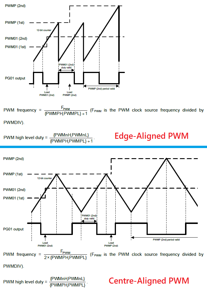
The first type was demonstrated in the simple PWM example. The second is demonstrated here. From the perspective of a general user, the difference in them don’t affect much. Make sure that you check the formulae for each type before using.
The set up for complimentary PWM with dead time is no different from the simple PWM set up. As mentioned, there are a few minor differences. First the mode is set for complimentary PWM mode. Secondly, centre-aligned PWM is used here. The outputs are also set as inverted outputs, i.e. 100% duty cycle means minimum PWM value/count. The dead time period is set and implemented.
P11_PushPull_Mode;
P12_PushPull_Mode;
PWM0_P12_OUTPUT_ENABLE;
PWM1_P11_OUTPUT_ENABLE;
PWM_COMPLEMENTARY_MODE;
PWM_CENTER_TYPE;
set_CLRPWM;
PWM_CLOCK_FSYS;
PWM_CLOCK_DIV_64;
PWM0_OUTPUT_INVERSE;
PWM1_OUTPUT_INVERSE;
set_PWM_period(600);
set_PWM_dead_time(40);
PWM01_DEADTIME_ENABLE;
set_PWMRUN;
Now what is dead time in complimentary PWMs? Well simply is a short duration delay that is inserted between the polarity shifts of two PWMs in a group.
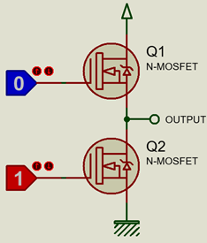
Consider a half-bridge MOSFET configuration as shown above. Perhaps it is the best way to describe the concept of dead-time. Surely, nobody would ever want to turn on both MOSFETs simultaneously in any condition and also during transition. Doing so would lead to a temporary short circuit between voltage source and ground, and would also lead to unnecessary heating of the MOSFETs and even permanent damage. By applying dead-time this can be avoided. In half/H-bridges, complimentary PWMs ensure that when one MOSFET is on, the other is off. However, at the edges of PWM polarity shifts, i.e. when one is rising while the other is falling, there is short but certain such short-circuit duration. If a dead time is inserted between the transitions, it will ensure that one MOSFET is only turned on when the other has been turned off fully.
Setting dead time requires us to disable TA protection. The function for setting dead time is shown below:
void set_PWM_dead_time(unsigned int value)
{
unsigned char hb = 0;
unsigned char lb = 0;
lb = (value & 0x00FF);
hb = ((value & 0x0100) >> 8);
BIT_TMP = EA;
EA = 0;
TA = 0xAA;
TA = 0x55;
PDTEN &= 0xEF;
PDTEN |= hb;
PDTCNT = lb;
EA = BIT_TMP;
}
Since complimentary PWMs work in groups, changing the duty cycle of one PWM channel will affect the other and so we don’t need to change the duty cycles of both PWMs individually. This is why only one PWM channel is manipulated in the code.
Demo
Wakeup Timer and Power Modes
One of key feature of many modern era microcontrollers is a way to wake up a micro once it went to low power, sleep or idle mode. Like STM8s, N76E003 has this feature. The wakeup timer (WKT) is not a complex hardware. As the block diagram below shows it is just a timer-counter with LIRC as clock source. When the counter overflows, an interrupt is triggered. This interrupt wakes up the N76E003 chip.

Wakeup timer is particularly very useful when used with low power modes. In many applications, we need to measure data on a fixed time basis while at other times when measurements are not taken, idle times are passed. These idle periods consume power and so if we use a wakeup timer with low power sleep mode, we can save energy. This is a big requirement for portable battery-operated devices. Examples of such portable devices include data-loggers, energy meters and smart watches.
Code
#include "N76E003_iar.h"
#include "Common.h"
#include "SFR_Macro.h"
#include "Function_define.h"
#include "soft_delay.h"
#pragma vector = 0x8B
__interrupt void WKT_ISR(void)
{
clr_WKTR;
clr_WKTF;
}
void main(void)
{
unsigned char s = 0;
P15_PushPull_Mode;
WKCON = 0x03;
RWK = 0X00;
set_EWKT;
set_EA;
while(1)
{
for(s = 0; s < 9; s++)
{
P15 = ~P15;
delay_ms(100);
}
set_WKTR;
set_PD;
for(s = 0; s <= 9; s++)
{
P15 = ~P15;
delay_ms(300);
}
set_WKTR;
set_PD;
};
}
Schematic

Explanation
In the demo demonstrated here, P15 LED is toggle fast for nine times. This marks the start of the demo. After this toggling has been done, both the wakeup timer and the power down modes are turned on.
set_WKTR;
set_PD;
During Power Down time, all operations inside the micro are suspended. There is also another low power mode called Idle Mode. Both are similar but in idle mode peripherals are kept active.

After the first set of LED toggles and power down mode, it takes about 1.5 seconds (according to the prescalar value of 64 and 256 counts) for the wakeup timer to get triggered.
![]()
When the interrupt kicks in, the MCU is brought back to working mode and the wakeup timer is disabled. Again, the P15 LED is toggled. This time the LED is toggled at a slower rate, indicating the continuation of the rest of the tasks after power down. After this the process is repeated with power down and wake up timer reenabled.
Setting up the wakeup timer requires the same stuffs that we need during a timer configuration, i.e. a prescalar value, counter value and interrupt. These three settings are done by the following lines of code:
WKCON = 0x03;
RWK = 0X00;
set_EWKT;
set_EA;
Since interrupt is used, WKT interrupt will be triggered when its counter rolls over.
#pragma vector = 0x8B
__interrupt void WKT_ISR(void)
{
clr_WKTR;
clr_WKTF;
}
When WKT interrupt is triggered, its interrupt flag should be cleared in the software.
Demo
Watchdog Timer
The watchdog timer (WDT) of N76E003 is just a reset-issuing timer and the purpose of this timer is to recover a N76E003 micro from an unanticipated event/loop that may result in unresponsive or erratic behaviour. It is clocked with LIRC oscillator and this makes it independent from main clock (HIRC or ECLK) failure.
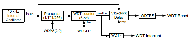
LIRC is prescaled and feed to a counter. When the counter overflows, WDT interrupt is issued, furthermore a reset is also generated based on delay. In normal running condition, the counter must be periodically reset to 0 count to avoid reset. If for some reason this is not done then a reset will be triggered.
The watchdog timer of N76E003 can also be used as a 6-bit general-purpose timer. However, this usually not used as such. The only difference between using it as timer and as a watchdog timer is the reset part.

Code
#include "N76E003.h"
#include "Common.h"
#include "Delay.h"
#include "SFR_Macro.h"
#include "Function_define.h"
void main (void)
{
unsigned char s = 0;
P15_PushPull_Mode;
Timer0_Delay1ms(1000);
for(s = 0; s <= 9; s++)
{
P15 = ~P15;
Timer0_Delay1ms(60);
}
TA = 0xAA;
TA = 0x55;
WDCON = 0x07;
set_WDCLR;
while((WDCON | ~SET_BIT6) == 0xFF);
EA = 1;
set_WDTR;
while(1)
{
for(s = 0; s <= 9; s++)
{
P15 = ~P15;
Timer0_Delay1ms(200);
}
while(1);
}
}
Schematic
Explanation
For demoing WDT, again the P15 LED is used. The code starts with it toggling states ten times. This marks the beginning of the code and the interval prior to WDT configuration.
Next the WDT is setup. Note that the WDT is Timed-Access (TA) protected. TA protection protects crucial hardware like brownout detection circuit and WDT hardware from erratic writes.

For using the TA hardware, we need not to follow any special procedure. To enable access to some hardware that are TA protected like the WDT all we have to do is to write the followings to TA register:
TA = 0xAA;
TA = 0x55;
Without TA protection access, any changes to made to the registers of the TA protected hardware is unaffected.
After enabling access to WDT, we can set it up. Setting the WDT requires us mainly to setup LIRC clock prescalar. Once the prescalar is set we are good to go for enabling the WDT.
WDCON = 0x07;
set_WDCLR;
while((WDCON | ~SET_BIT6) == 0xFF);
set_EA;
set_WDTR;
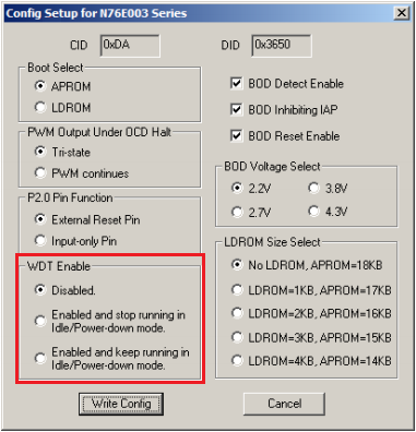
Before all these can be done, we have to enable the WDT hardware either through In-Application Programming (IAP) or by configuration bits during programming.
Demo
|
|
Thank you very much for reply sir.
From Trailing explanation ,I understand from this, variable ‘overflow’ stores the time and variable ‘end_time’ catches the residual time when capture interrupt occurs and Timer2 under running mode just before overflow. Is my understanding is correct?
Further, what is the speed of Timer 2 under free running, is it 8MHz? Means it overflows at speed 1/8MHz till counter reaches 65536. (TH2=FF and TL2=FF).
Moreover, in equation (overflow << 16) let consider variable overflow=2; bit shift left make the integer
1,048,576 is my understanding correct?
Furthermore, Timer1 is continuous in interrupt mode as TH1=0, TL1=0, then how interrupt of Timer2 happen as priority of Timer2 is less also as capture?
Sir, could you please help to clear my confused understanding!!
With Regards,
ASHAH
Thank you very much for reply sir.
From trailing explanation, I understand from this, variable ‘overflow’ stores the time and variable ‘end_time’ catches the residual time when capture interrupt occurs and Timer2 under running mode just before overflow. Is my understanding is correct?
Further, what is the speed of Timer 2 under free running, is it 8MHz? Means it overflows at speed 1/8MHz till counter reaches 65536. (TH2=FF and TL2=FF).
Moreover, in equation (overflow << 16) let consider variable overflow=2; bit shift left make the integer
1,048,576 is my understanding correct?
Furthermore, Timer1 is continuous in interrupt mode as TH1=0, TL1=0, then how interrupt of Timer2 happen as priority of Timer2 is less also as capture?
Sir, could you please help to clear my confused understanding!!
With Regards,
ASHAH
Hi,
Sir, could you please explain the equation “pulse_time = ((overflow << 16) – start_time + end_time);" in capture mode. Means what is the use of overflow by rotate left 16. If you can explain by giving example will be very useful to us.
Thank You.
Regards,
ASHAH
The timer used in that code is 16-bit wide and so shifting the variable overflow (which increments when a timer overflow event occurs) by 16 is a way of taking account of overflow event. Now suppose the time captured is when the timer’s count is nearing an overflow event, we have to take account of the overflow too. This is needed for capturing times for a low frequency signal in which case the timer may overflow and if overflow is not taken into account then the result may be erroneous.
Thank You very much for reply.
From the answer I understand, as Timer 2 is in continuous counting mode & reload when overflow occurs with increment value of variable ‘overflow’ till capture interrupt happens. Here, variable ‘overflow’ will increase at each interrupt from Timer 2. So, ‘overflow’ variable gives total time & ‘end_time’ is fraction of time which is under process towards overflow of the timer 2 but in between capture interrupt happens. Is my understanding is correct , Sir ?
Then, I have one more question that as Timer 2 is under free running mode, what is the speed, means how much time it takes to generate interrupt? in micro or millisecond because timer2 overflow happens at count value 65536(as 16 bit timer with TH2=FF and TL2=FF).
Also, if value of variable overflow is let consider 2 then 2 <> 8); TL1 = (value & 0x00FF); due to variable ‘value’ =0; Then how timer 2 will give interrupt as Timer 1 is having higher priority.
Kindly reply to clear my confused understanding.
Thank You.
Best Regards,
ASHAH
Thank you very much for reply sir.
I understand from this, variable ‘overflow’ stores the time and variable ‘end_time’ catches the residual time when capture interrupt occurs and Timer2 under running mode just before overflow. Is my understanding is correct?
Further, what is the speed of Timer 2 under free running, is it 8MHz? Means it overflows at speed 1/8MHz till counter reaches 65536. (TH2=FF and TL2=FF).
Moreover, in equation (overflow << 16) let consider variable overflow=2; bit shift left make the integer
1,048,576 is my understanding correct?
Furthermore, Timer1 is continuous running in interrupt mode as TH1=0, TL1=0, then how interrupt of Timer2 happen as priority of Timer2 is less also as capture?
Sir, could you please help to clear my confused understanding!!
With Regards,
ASHAH
Thank you very much for reply sir.
I understand from this, variable ‘overflow’ stores the time and variable ‘end_time’ catches the residual time when capture interrupt occurs and Timer2 under running mode just-before overflow. Is my understanding is correct?
Further, what is the speed of Timer 2 under free running, is it 8MHz? Means it overflows at speed 1/8MHz till counter reaches 65536. (TH2=FF and TL2=FF).
Moreover, in equation (overflow << 16) let consider variable overflow=2; bit shift left make the integer
1,048,576 is my understanding correct?
Furthermore, Timer1 is continuous in interrupt mode as TH1=0, TL1=0, then how interrupt of Timer2 happen as priority of Timer2 is less also as capture?
Sir, could you please help to clear my confused understanding!!
With Regards,
ASHAH
Thank you very much for reply sir.
I understand from this, variable ‘overflow’ stores the time and variable ‘end_time’ catches the residual time when capture interrupt occurs and Timer2 under running mode just before overflow. Is my understanding is correct?
Further, what is the speed of Timer 2 under free running, is it 8MHz? Means it overflows at speed 1/8MHz till counter reaches 65536. (TH2=FF and TL2=FF).
Moreover, in equation (overflow << 16) let consider variable overflow=2; bit shift left make the integer
1,048,576 is my understanding correct?
Furthermore, Timer1 is continuous in interrupt mode as TH1=0, TL1=0, then how interrupt of Timer2 happen as priority of Timer2 is less also as capture?
Sir, could you please help to clear my confused understanding!!
With Regards,
ASHAH
Thank you very much for reply sir.
I understand from this, variable ‘overflow’ stores the time and variable ‘end_time’ catches the residual time when capture interrupt occurs and Timer2 under running mode just before overflow. Is my understanding is correct?
Regards,
ASHAH
Thank you very much for reply sir.
I understand from this, variable ‘overflow’ stores the time and variable ‘end_time’ catches the residual time when capture interrupt occurs and Timer2 under running mode just before overflow. Is my understanding is correct?
Further, what is the speed of Timer 2 under free running, is it 8MHz? Means it overflows at speed 1/8MHz till counter reaches 65536. (TH2=FF and TL2=FF).
Moreover, in equation (overflow << 16) let consider variable overflow=2; bit shift left make the integer
1,048,576 is my understanding correct?
Furthermore, Timer1 is continuous in interrupt mode as TH1=0, TL1=0, then how interrupt of Timer2 happen as priority of Timer2 is less also as capture?
Sir, could you please help to clear my confused understanding!!
With Regards,
ASHAH
Thank you very much for reply sir.
I understand from this, variable ‘overflow’ stores the time and variable ‘end_time’ catches the residual time when capture interrupt occurs and Timer2 under running mode just before overflow. Is my understanding is correct?
Further, what is the speed of Timer 2 under free running, is it 8MHz? Means it overflows at speed 1/8MHz till counter reaches 65536. (TH2=FF and TL2=FF).
Moreover, in equation (overflow << 16) let consider variable overflow=2; bit shift left make the integer
1,048,576 is my understanding correct?
Furthermore, Timer1 is continuous in interrupt mode as TH1=0, TL1=0, then how interrupt of Timer2 happen as priority of Timer2 is less also as capture?
Sir, could you please help to clear my confused understanding!!
With Regards,
ASHAH
Hi,
Could you please reply on my understanding please.
Regards,
ASHAH
Already replied but which part you do not understand?
Thank You for reply.
Regards
Ankur
Hi,
Please share details for phase angle measurement between two of Three phase system using capture mode.
I used hardware with DC offset method of 2.5Vdc.
Regards.
Dear Sir,
With Nuvoton, how we can make button event programming, single push button, long press, short press and double click, with program can you please help me?
hi,i want to know that i want a timer with interrupt after every 100microsecond i.e timer0 in mode 1 so what should be the fsys .
Dear Sir,
May I ask? In your example for Timer0, saw that you set the CKDIV at 80 as timer count prescaler, will this impact everything that use internal clock source or CKDIV just applies for timers only? I want to write another version look-a-like millis() in Arduino AVR for precision time management and plan to get Timer0 to do that. It seems that Timer0 doesn’t have clock divider on it own, only Timer3 (sorry I missed anything, I tried to read through N76E003 datasheet for timers).
Or you can suggest a better way to get millis() implemented for N76E003? Something count up from the start of the chip but we don’t need it updates counting too fast…
CKDIV is set with a value of 80 to make the system clock, peripherals and flash memory to run at 100 kHz speed. It affects not just timers but everything.
Why go for Arduino-like millis function when you have hardware-based input capture?
hello sir
when timer 0 or 1 is in mode 3 ,is it possible to run both timer along with timer1 can use as baud rate generator? why timer as used in application like baud rate generator in nuvoton?
8051 architecture demands the usage of timer for baud rate generation since there is no dedicate baud rate generator unlike other microcontrollers. If a timer is being used for baud rate generation, it is better to leave it for that purpose only and use other timer for other tasks….
How can i calculate minimum ISR interval for nuvoton -8051(8bit)?
From below sample code for nuvoton 8051 timer0 mode 0, the isr interval is calculated is 1ms,
its work. but how can I calculate the minimum isr timer interval for 16mhZ frequency.?
#define TH0_INIT 0x1A //1.0ms@XTAL=16MH
#define TL0_INIT 0xEC
while loading these hex values gets 1ms Isr interval. I was tried 5-microsecond calculation for timer 0, but not get the correct 5uS interval.
#include “N76E003.h”
#include “Common.h”
#include “Delay.h”
#include “SFR_Macro.h”
#include “Function_define.h”
#define TH0_INIT 0x1A //1.0ms@XTAL=16MH
#define TL0_INIT 0xEC
#define TH1_INIT 0xD7
#define TL1_INIT 0x0C
/************************************************************************************************************
* TIMER 0 interrupt subroutine
************************************************************************************************************/
void Timer0_ISR (void) interrupt 1 //interrupt address is 0x000B
{
TH0 = TH0_INIT;
TL0 = TL0_INIT;
// GPIO toggle when interrupt
}
/************************************************************************************************************
* TIMER 1 interrupt subroutine
************************************************************************************************************/
//void Timer1_ISR (void) interrupt 3 //interrupt address is 0x001B
//{
// TH1 = TH1_INIT;
// TL1 = TL1_INIT;
// P12 = ~P12; // GPIO toggle when interrupt
//}
/************************************************************************************************************
* Main function
************************************************************************************************************/
void main (void)
{
//TMOD = 0XFF;
Set_All_GPIO_Quasi_Mode;
TIMER0_MODE0_ENABLE; //Timer 0 and Timer 1 mode configuration
// TIMER1_MODE0_ENABLE;
clr_T0M;
clr_T1M;
TH0 = TH0_INIT;
TL0 = TL0_INIT;
// TH1 = TH1_INIT;
// TL1 = TL1_INIT;
set_ET0; //enable Timer0 interrupt
//set_ET1; //enable Timer1 interrupt
set_EA; //enable interrupts
set_TR0; //Timer0 run
//set_TR1; //Timer1 run
while(1)
{
}
}
With these settings i.e. TL0 and TH0 = 0x1AEC (6892 in Decimal) the timing is calculated as follows:
ISR Time = (8192 – 6892) / (16MHZ / 12) = 0.975ms or 1ms…. Timer 0 is in 13-bit mode and so the top value of the timer is 8192 and FOSC (16MHz) is divided by 12 because T0M = 0….
I hope now you can find the minimum ISR time….
Sir,
when i calculated ISR time 10 micro second(timer0 mode0,16MHZ) ,got decimal value 8179.
while analyzing using CRO, nearly got correct interval(10uS). but when i place some conditions inside the ISR(shown below) ,the ISR interval changes double .why this happens?
void Timer0_ISR (void) interrupt 1 //interrupt address is 0x000B
{
P12 = ~P12;
a++;
if(a>100000)
{
a=0;
b=1;
}
TL0 =u8TL0_Tmp;
TH0 = u8TH0_Tmp;
}
Pin toggling is basically a two state process. You have a high time and a low time. Your CRO is measuring both of these times and so you are getting double ISR interval. Lastly, you can go to minimum time ceiling when it comes to interrupts. There are instructions that are present in the interrupt service routine that need time to execute. If there is an interrupt while processing these instructions, you may get undesired outcomes.
thanks for you replay ,
sir… is it really possible to generate 10 micro second ISR interval using timer in nuvoton?
is it possible generate other timer intervals like 1 Second ,2 Second ,etc using same ISR which is run at 10 micro second .
Yes it is possible to use one timer for various intervals while keeping the ISR interval fixed….
Check this sample code for a timer-based RTC:
void RTC()

{

         set_timer1(tmr1_load);

         s += 1;

         toggle = ~toggle;

         if(s > 59)

         {

                  s = 0;

                  min += 1;

                  if(min > 59)

                  {

                           min = 0;

                           hr += 1;

                           if(hr > 23)

                           {

                                    hr = 0;

                           }

                  }

         }
}
Here the timer is ticking at 1000ms timer ISR interval…. Inside the ISR, the second variable is increment and this in turn increments minutes and hours….
Good day, mr. Shawon Shahryiar
I have a question about “Simple PWM – RGB LED Fading”
Is it possible to make a phase shift 120 degrees between three channels? Frecuency, Duty cycle (needs 1-5%) are same for 3 channels in this case .
Yes it is possible….
Dear Sir,
Thank you for valuable guidance for beginner like me
due to all your post I’m able to create a program which is based on mode selection for temp controller.
but I’m unable to make it with timer control as i want to switch off the program after 30 min, using internal frequency only can you please guide me which timer I need to use so that I can switch OFF the program after 30 min
I want to make time base control using Nuvoton N76E0003 please guide me.
Did you the read the article? If you have any confusion, please be specific….
For 30 minute I suggest you go for interrupt method and do as I did with the stopwatch code, i.e use variables to track time….
Yes I read your article as being first time doing micro controller programming i made program.
with the help push button I made my LED on now I want to make it OFF after 30 min from the instance I pressed my push button to make this LED on, i want to use internal crystal frequency only.
please guide me with more simple codes using Keil software.