Lab 11: Multiplexing seven segment LED displays

|
|
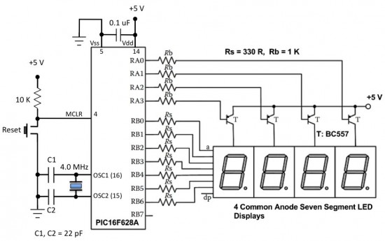
In Lab 6, we discussed about interfacing a seven segment LED display to a PIC microcontroller. The seven segments were driven individually through separate I/O pins of the microcontroller. If we do just like that then for 4 seven segment LED displays, 28 I/O pins will be required, which is quite a bit of resources and is not affordable by mid-range PIC microcontrollers. That’s why a multiplexing technique is used for driving multiple seven segment displays. This tutorial shows how to multiplex 4 common anode type seven segment LED displays with a PIC16F628A microcontroller.
Circuit Diagram
The theory behind the multiplexing technique is simple. All the similar segments of multiple LED displays are connected together and driven through a single I/O pin. In the circuit below, the seven segments are connected to PORTB through current limiting resistors Rs. A particular segment is active when the corresponding PORTB pin is low. However, it will not glow until it’s anode is connected to Vcc. You can see the anodes of the four LED displays are not directly connected to Vcc. Instead, 4 PNP transistors are used as switches to connect or disconnect the anode terminals from Vcc. When the base of the PNP transistor is low, the transistor conducts and corresponding digit’s common anode is connected to Vcc. Therefore, the transistor selects which displays is active. The conduction of the transistors are controlled by RA0 through RA3 pins of PORTA. Suppose, if we want to display 7 in the units digit place, then segments a, b, and c should be turned on first (which means RB0, RB1, RB2 are 0 and RB3-RB6 are 1) and then RA0 should be pulled low (while keeping RA1-RA3 high) so that only units digit display will be active. In order to display all 4 digits, each seven-segment display is activated sequentially using an appropriate refresh frequency so that it will appear that all the them are turned on at the same time.
Software
A sample program for a 4-digit up counter is developed using the MikroC compiler. The counter starts with 0, increments every second up to 9999, and reset to zero. The value of the counter is displayed on the four 7-segment LED displays. The complete program is described here. The function mask() takes in a numeric digit from 0-9 and returns the value for PORTB that will turn the selected LEDs on to display that particular number. For example, if the digit to be displayed is 1, then it requires segments b and c to be turned on. So the function mask() will return value 0xF9 (0b11111001) for PORTB, that will turn on the LED segments b and c. Remember that the return values of mask() function would be different (complement of the current values) if the LED display is common cathode type.
/*
 * Project name:
    Decimal UP Counter with Four 7-Segment Display Multiplexing
 * Copyright:
     (c) Rajendra Bhatt, 2011.
 * Description:
     This code is an example of multiplexed Seven Segment Displays.
     MCU:  PIC16F628A, 4.0 MHz external clock, MCLR Enabled
     The common anodes of four seven segment dispalys are
     connected to RA0, RA1, RA2 and RA3, whereas the seven
     segments are driven through PORTB pins
*/

unsigned short i, DD0, DD1, DD2, DD3;
unsigned int Count;
//------ Function to Return mask for common anode 7-seg. display
unsigned short mask(unsigned short num) {
 switch (num) {
 case 0 : return 0xC0;
 case 1 : return 0xF9;
 case 2 : return 0xA4;
 case 3 : return 0xB0;
 case 4 : return 0x99;
 case 5 : return 0x92;
 case 6 : return 0x82;
 case 7 : return 0xF8;
 case 8 : return 0x80;
 case 9 : return 0x90;
 } //case end
}
void main() {
  CMCON  |= 7;        // Disable Comparators
  TRISB = 0x00; // Set PORTB direction to be output
  PORTB = 0xff;    // Turn OFF LEDs on PORTB
  TRISA = 0b00100000; // RA5 is input only
  Count   =    0;  // Initial Value of Counter

  do {
  DD0 = Count%10;  // Extract Ones Digit
  DD0 = mask(DD0);
  DD1 = (Count/10)%10; // Extract Tens Digit
  DD1 = mask(DD1);
  DD2 = (Count/100)%10; // Extract Hundreds Digit
  DD2 = mask(DD2);
  DD3 = (Count/1000);  // Extract Thousands Digit
  DD3 = mask(DD3);

  for (i = 0; i<=50; i++) {
      PORTB = DD0;
      RA0_bit = 0;      // Select Ones Digit
      RA1_bit = 1;
      RA2_bit = 1;
      RA3_bit = 1;
      delay_ms(5);
      PORTB = DD1;
      RA0_bit = 1;
      RA1_bit = 0;     // Select Tens Digit
      RA2_bit = 1;
      RA3_bit = 1;
      delay_ms(5);
      PORTB = DD2;
      RA0_bit = 1;
      RA1_bit = 1;
      RA2_bit = 0;     // Select Hundreds Digit
      RA3_bit = 1;
      delay_ms(5);
      PORTB   = DD3;
      RA0_bit = 1;
      RA1_bit = 1;
      RA2_bit = 1;
      RA3_bit = 0;     // Select Thousands Digit
      delay_ms(5);
      }
      Count = Count + 1 ;
      if (Count > 9999) Count = 0;
  } while(1);          // endless loop
}
Download the project source (MikroC) and HEX files
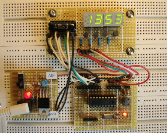
After the program is loaded in to the microcontroller, power the circuit and watch the 4-digit up-counter running.
|
|


Sir
Can you tell me programming of 0 to 99
For single port PIC16F877A
Hello guys, Could you please explain for me the following experiment in an easier way to understand and also some links of videos that I can watch to help me build this circuit.
“Demonstrate how to manually operate a serial display that uses two seven segment displays with decoders, latch and a shift register.”
Thanks!
HOW TO WRITE 8085 PROGRAM FOR THIS STATEMENT?
For Kalpesh.
Buddy can u help me in solving this thing.
If i got the hardwares where the a-h of 7-seg are connected to various pins of diff ports. Then how to run your count program on that.
hi guys, am having problem with this code,please help me to solve as soon as possible,its urgent
error: expression syntax
#include
#include
//#include
#include
unsigned short i,DD0,DD1,DD2,DD3;
unsigned short DD01,DD11,DD21,DD31;
unsigned int count;
void DelayMs(unsigned int Ms);
unsigned char mask[11]={0x81,0xf3,0x49,0x61,0x33,0x25,0x05,0xf1,0x01,0x21,0xfe};
void main()
{
CMCON != 7;
INTCON = 0;
ADCON1 = 0b00001111;
TRISC = 0x00;
TRISA2 = 0B00000100;
TRISA3 = 0B00001000;
TRISD2 = 0B00000100;
TRISD3 = 0B00001000;
do
{
for(i = 0,count = 0; i <= 9999,count 9999)
count = 0;
//}
}
}while(1);
}
void DelayMs(unsigned int Ms)
{
int delay_cnst;
while(Ms > 0)
{
Ms–;
for(delay_cnst = 0;delay_cnst <= 15256 ;delay_cnst++);
}
}
HI guys,am having problem with this code please help me to solve,its urgent please reply as soon as possible
error : expression syntax
#include
#include
//#include
#include
unsigned short i,DD0,DD1,DD2,DD3;
unsigned short DD01,DD11,DD21,DD31;
unsigned int count;
void DelayMs(unsigned int Ms);
unsigned char mask[11]={0x81,0xf3,0x49,0x61,0x33,0x25,0x05,0xf1,0x01,0x21,0xfe};
void main()
{
CMCON != 7;
INTCON = 0;
ADCON1 = 0b00001111;
TRISC = 0x00;
TRISA2 = 0B00000100;
TRISA3 = 0B00001000;
TRISD2 = 0B00000100;
TRISD3 = 0B00001000;
do
{
for(i = 0,count = 0; i <= 9999,count 9999)
count = 0;
//}
}
}while(1);
}
void DelayMs(unsigned int Ms)
{
int delay_cnst;
while(Ms > 0)
{
Ms–;
for(delay_cnst = 0;delay_cnst <= 15256 ;delay_cnst++);
}
}
Can any one provide me Proteus Design for this Circuit ?
kalpesh on January 14th, 2013 4:22 am
Thanks for this useful multiplexing.
But I’m like Kalpesh I think there is another problem
I think we must clear portb ( PORTB = 0xFF;) before we displaying the second digit,
I use your code like this but with small modify on code by adding this ( PORTB = 0xFF;)
Please take a look at this code:
for(i=0;i<=50;i++)
{
PORTB=DD0; // Select Ones Digit
seg1=1;
seg2=0;
seg3=0;
seg4=0;
delay_ms(5);
PORTB=0XFF;
PORTB=DD1; // Select Tens Digit
seg1=0;
seg2=1;
seg3=0;
seg4=0;
delay_ms(5);
PORTB=0XFF;
PORTB=DD2; // Select Hundreds Digit
seg1=0;
seg2=0;
seg3=1;
seg4=0;
delay_ms(5);
PORTB=0XFF;
PORTB=DD3; // Select Thousands Digit
seg1=0;
seg2=0;
seg3=0;
seg4=1;
delay_ms(5);
PORTB=0XFF;
}
Thanks for advance
Best regards.
Sallam
Using this type of display coding, can you blank the leading zeros? If so, could you please show the necessary additional coding?
thx bro you are really good man
but i need your help and im very thankful to this site
can you please help me to make a real time clock using 16f877 and ds 1307 and 6 seven segment because in all other website i cant find good explanaition and all the real time project are shown on lcd
thank you sir for helping me
in the code
1- u make count=count+1 and u dont mention any time delay how count++ every 1 sec
2- why u make i and i++ and i<=50
Man you r really helpful man thanxs very much i really learn the micro controller programming from your examples
yes RAj you’re right 😀
Hi Raj,
I wanted some help in adding a feature to the project Multiplexing seven segment LED displays,wondering if you can help me.I want to store the count value in the eeprom so when the power is turned off and turned on again also it gives me the previous value.looking forward for your reply.
Regards
Harsha
Yes, Theres problem in code. This code runs fine in Proteus but it wont run in physical hardware, Because problem is very simple. Just check those
for (i = 0; i<=50; i++) {
PORTB = DD0;
RA0_bit = 0; // Select Ones Digit
RA1_bit = 1;
RA2_bit = 1;
RA3_bit = 1;
delay_ms(5);
PORTB = DD1;
RA0_bit = 1;
RA1_bit = 0; // Select Tens Digit
RA2_bit = 1;
RA3_bit = 1;
delay_ms(5);
PORTB = DD2;
RA0_bit = 1;
RA1_bit = 1;
RA2_bit = 0; // Select Hundreds Digit
RA3_bit = 1;
delay_ms(5);
PORTB = DD3;
RA0_bit = 1;
RA1_bit = 1;
RA2_bit = 1;
RA3_bit = 0; // Select Thousands Digit
delay_ms(5);
}
here there should be 1 instead of 0 and 0 instead of 1. So make sure you guyz change before working hardware circuit. I have checked everything myself and i found the problem. Proteus simulates wrong logic…
The program is correct for common anode displays (used in this tutorial) driven by PNP transistors. If you have to change 0s to 1s and 1s to 0s to make this work, you might be using NPN transistors with collector and emitters reversed.
good morning
im sorry but we can’t read the number from when we run this code they are not cleaar enought and we can’t see clear the changing number from one to two for example can you help me to make it clear enough
now its fine 🙂
Correct code is given above in the article.
unsigned short i, DD0, DD1, DD2, DD3;
unsigned int Count;
//—— Function to Return mask for common anode 7-seg. display
unsigned short mask(unsigned short num) {
switch (num) {
case 0 : return 0x3F;
case 1 : return 0x06;
case 2 : return 0x5B;
case 3 : return 0x4F;
case 4 : return 0x66;
case 5 : return 0x6D;
case 6 : return 0x7D;
case 7 : return 0x07;
case 8 : return 0x7F;
case 9 : return 0x6F;
} //case end
}
void main() {
CMCON |= 7; // Disable Comparators
TRISB = 0x00; // Set PORTB direction to be output
PORTB = 0xff; // Turn OFF LEDs on PORTB
TRISA = 0b00100000; // RA5 is input only
Count = 0; // Initial Value of Counter
do {
DD0 = Count%10; // Extract Ones Digit
DD0 = mask(DD0);
DD1 = (Count/10)%10; // Extract Tens Digit
DD1 = mask(DD1);
DD2 = (Count/100)%10; // Extract Hundreds Digit
DD2 = mask(DD2);
DD3 = (Count/1000); // Extract Thousands Digit
DD3 = mask(DD3);
for (i = 0; i 9999) Count = 0;
} while(1); // endless loop
}
is the correct code…for mikroc
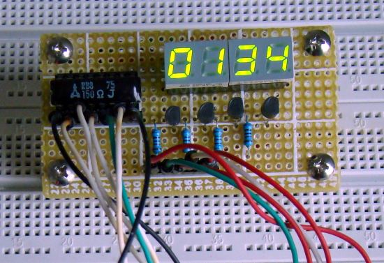
Sorry if my question is stupid but what is that chip beside the 7-segments? In the schematic all the 7-seg pins are connected to PIC16F628A via resistors. But there is another chip in the first picture. what is that?
That’s a chip resistor and contains 8 resistors for limiting current through LED segments.
Slim! J’peux te faire ca moi! 🙂
bientot
A+!
marC:)
daer r-b can i use heart rate sensor ???
hello dear r-b what is the sensor here????? it’s same as heart rate ???
ahmed from technical engineering college …..
thank
Bonsoir
Pourrier-vous modifier le programme du chronomètre ajouter les deux boutons poussoires
1 Bouton sur la broche RA4 = START_PAUSE
1 Bouton sur la broche RB7 = REPRISE
Cdl
Slim
Great article thanks! just one doubt. What if the leds are 12V @40mA 3 led bars (I believe the code is STR33R per segment) I can add an ULN2003 to provide the grounds (sink) but what about the PNP transistor to switch the displays and its base resistor? How can I calculate for the necessary changes ? thank you so much in advance. Great Tutorial once again!
This is one of the best tutorial i have came across regarding seven segment.
It is very useful for me. Please send to me, if you have this type of hex file with source code.
thank you much,
bala.R
Thankyou, when I read my comments I noted my typo error.
Regards
Hello.
Some advice please. I’m playing around with multiplexing some CA and CC LED displays and need to understand the correct configuration for the Transistors.
For a CA display would you use a PNP transistor with the Collector connected to the anode, Emitter to +V and the base connected to your required IP
For a CC display would you use a NPN transistor with the Collector connected to the anode, Emitter to Gnd and the base connected to your required IP.
Is this correct ?
Thank you
Kevin,
For CC you would connect the collector to the common cathode. Rest of whatever said is correct.
what are the things i need to change if i am gonna implement this code on a PIC16f84a?
I d like to bring it to your notice that because the transistors are PNP and NOT NPN, pulling the base low will allow the transistor to conduct and not the other way as you mentioned in the article.
Just a typo probably.
Thank you Krishi for pointing that.
Have you had anybody ask to read minutes and seconds on the display – I’m sure this is possible with a minor change, please advise, have you done this, or know of someone who has?
Many thanks.
Bob……….South Africa
pic16f628 include internal clock
so no need to use external clock
but really good job
Is picstart use as a device programmer in this said device?
Pingback: 89c51 with keypad displaying on 4 seven segment
You have to give a delay (say 1000ms)
Line # 45 doesn’t have the modulus operator
line # 45 : DD3 = (Count/1000)%10; // Extract Thousands Digit
please send me scrolling message display asm code.i understant asm language . i want to built this circuit my hooby test. i need 8X128 display asm code with pic 16f84 please help me.thanks
beginner’s question 2:
when downloading a program, does the fuses and oscillator settings take a big role? I mean, is there the possibility not to run when messing with the wrong or none fuses settings?
That’s true.
beginner’s question: just that compiled .hex file must be downloaded to the microcontroller to work, right? the other files are just source codes for various programming languages?
@jimday,
You got it right. Only the HEX file should be loaded in to the microcontroller.
So Rajendra,
Can you help me with that serial programmer, pretty please with sugar lumps on it?
@jimday,
Which serial programmer are you talking about? If you are looking for a low-cost programmer, read this:
http://embedded-lab.com/blog/?p=641
The serial programmers may not run in all computers.
In the text at the circuit diagram, in the first parenthesis shouldn’t be rb3-rb6? Because the first three are low rb0,rb1,rb2; so rb3 to rb6 are high. If I understood correctly.
@jimday,
Thank you for correcting that.
Sir’
“Download the project source (MikroC) and HEX” files Not Found.
Please Help me.
Arif,
Try now, it should work.
I like that you used a PIC with an 8 bit wide latch. The last tutorial with the PIC16F688 has more complicated code because you couldn’t just set
PORTB=whateverlike you can with the 628.I know what you are saying, Matt.
Pingback: Electronics-Lab.com Blog » Blog Archive » Multiplexing Seven Segment LED Displays