Lab 16: Understanding Interrupts
|
|
Interrupts are powerful concept in embedded systems for controlling events in a time-critical environment. In a typical embedded system, the embedded processor (microcontroller) is responsible for doing more than one task (but can do only one at a time). For example, let’s say in a programmable digital room thermostat, the microcontroller is assigned to monitor the room temperature, turn the AC or heater ON and OFF, control the LCD display, and respond to any new temperature setting from the user. Out of these the first three tasks are non-time-critical and are executed continuously in sequence one after the other, within the main loop. But when the user presses any button on the setting panel, the microcontroller should be able to read it before the user releases the button. So this is a time-critical event and the microcontroller should stop whatever it is doing and respond to this higher priority event. This is possible through the use of interrupts. This tutorial first describes the interrupt system in general and then illustrates how it is handled in PIC micrcontrollers.

Understanding interrupts in PIC microcontrollers
Theory
As mentioned above, interrupts form the basis for separating the time-critical events from the others and execute them in a prioritized manner. An interrupt tells the microcontroller to drop whatever it is doing and execute another program (the Interrupt Service Routine or ISR) stored at a predefined place in the program memory. Interrupt requests are asynchronous events which means that an interrupt request can occur at any time during the execution of a program. But whenever it occurs, the CPU finishes the current instruction and stores the address for the next instruction (which is in the Program Counter, or PC) in to the stack memory so that the current program can continue once the interrupt service ends. The CPU then jumps to a certain program memory location (0x0004 in the PIC), where the ISR begins. At the end of the ISR, execution of the return instruction loads the address at the top of the stack back into the program counter, and execution proceeds from the same point where the processor was interrupted.
A microcontroller has several sources of interrupts, which can be external or internal. The most common internal interrupt sources are timers, EEPROM, ADC module, and comparator. External interrupts originate in peripherals and reach the microcontroller through one of its pins and associated ports.
The PIC16F688 has the following sources of interrupt:
• External Interrupt at RA2/INT pin
• TMR0 Overflow Interrupt
• PORTA Change Interrupts
• 2 Comparator Interrupts
• A/D Interrupt
• Timer1 Overflow Interrupt
• EEPROM Data Write Interrupt
• Fail-Safe Clock Monitor Interrupt
• EUSART Receive and Transmit interrupts
Each of these interrupts can be enabled or disabled individually, and more than one interrupt can be active at the same time. When an interrupt is requested, the microcontroller finishes executing the current instruction, stores the value of the program counter in the stack, and jumps to address 0004h in program memory, where the ISR is located. As all interrupt sources make the program to jump to the same place (0004h), the programmer, when writing the ISR, must first find out the source that requested the interrupt. This is done by reading the appropriate bits in the special function registers, INTCON and PIR1, associated with the interrupt system. The figure below shows the bits in the interrupt control register (INTCON).

INTCON register bits in PIC16F688
The details for each bit are described here:
GIE (global interrupt enable): This bit is the master switch for all interrupts. Turn it off (GIE = 0) and no interrupts are enabled (regardless of the state of their individual enable bits). Turn it on (GIE = 1) and interrupts whose individual enable bits are set will be enabled. When an interrupt is requested, this bit is automatically set to 0, thus disabling any further interrupts. The return instruction at the end of the interrupt service subroutine sets bit GIE back to 1, thus enabling the global interrupt system.
PEIE (peripheral interrupt enable) is a mini-master switch for a group of interrupts which are known as ‘peripheral interrupts’. They have their own enable bits in the PIE1 register (discussed later). This bit must be set to enable any enabled peripheral interrupts.
T0IE, T0IF: These bits are related to Timer0 overflow interrupt. When T0IE = 1, the Timer0 interrupt is enabled. T0IF is set to 1 whenever TMR0 overflows from 255 to 0. This has been discussed in PIC Timers and Counters article too.
INTE, INTF: These bits are related to the external interrupt which depends on the state of the RA2/INT pin of PIC16F688. Bit INTE enables this interrupt. The interrupt can be set to trigger on the rising edge or falling edge of the signal on INT pin. This is done using the bit 6 (INTEDG) of the OPTION register (shown below). Bit INTF is a flag that indicates the detection of an edge (rising or falling) in the input pin INT.
RAIE, RAIF: These bits are related to the interrupt due to a change of logic level at PORTA pins. RAIE = 1 enables this interrupt and RBIF is a flag that indicates a change in one of the pins of PORTA. In order to select which PORTA pin should be able to trigger the interrupt, the corresponding bit of INTERRUPT-ON-CHANGE PORTA (IOCA) register must be set.
The individual bits of OPTION, PIE1 and IOCA registers are shown in the figures below.

INTEDG bit of OPTION_REG is used to set the edge select for interrupt on INT pin. Please read the datasheet of PIC16F688 for details on the functions of other bits.

Setting an IOCA bit enables the interrupt-on-change on the corresponding PORTA pin

PIE1 register bits are to enable the peripheral interrupts

PIR1 register contains the flag bits for peripheral interrupts and are set during interrupt conditions.
Please read datasheet of PIC16F688 for the detail description of these registers. In the following section, we will discuss how to program the interrupt that originates in the RA2/INT line of PIC16F688.
In order to initialize the RA2/INT interrupt, the following operations must take place:
1. Port-A, line 2 (RA2), must be initialized for input.
2. The interrupt source must be set to take place either on the falling or the rising edge of
the signal using INTEDG bit of OPTION_REG.
3. The external interrupt flag (INTF in the INTCON Register) must be initially cleared.
4. Global interrupts must be enabled by setting the GIE bit in the INTCON Register.
5. The External Interrupt on RA2/INT must be enabled by setting the INTE bit in the INTCON
Register.
A sample program using the RA2/INT interrupt is developed later in this article.
Circuit Diagram
In the circuit diagram shown below, a push button switch is wired to the RA2 port of PIC16F688. This switch produces the interrupt when pressed. Four red color LEDs are connected to RC0 through RC3 port and an yellow LED is wired to port RA0. The main program is a 4-bit binary up counter that increments at a rate of approximately one second. The value of the counter is sent to PORT-C and displayed on the four red LEDs. The yellow LED is toggled on and off when the pushbutton switch is pressed. The switch is active low and therefore, the interrupt is programmed on the falling edge of the signal (INTEDG = 0). The PIC16F688 runs at 4.0 MHz clock derived from the internal source.

Circuit diagram for demonstrating external interrupt handling in PICMicro

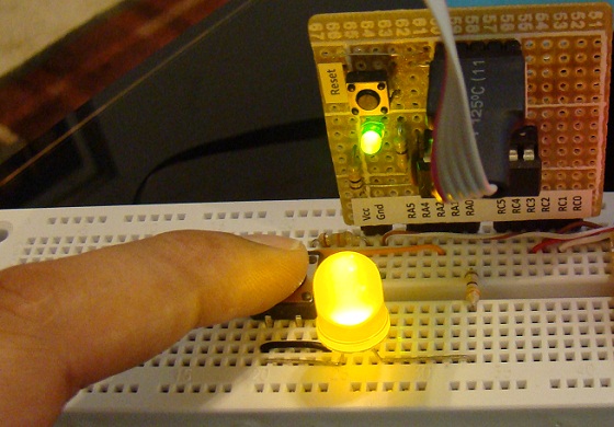
Circuit setup on breadboard
Software
The Interrupt Service Routine (ISR) depends on the specific application. However, certain steps are applicable to all cases. For example, the ISR should begin by checking which particular event triggered the interrupt (if more than one input is enabled). In this case, the INTF bit of INTCON register must be checked to verify that the source of interrupt is from RA2/INT pin. Similarly, the interrupt flag (INTF bit in INTCON register) must be cleared by the ISR before returning to the main program otherwise an endless series of interrupts will occur. This is because on return the CPU finds the interrupt flag still set and assumes it as another interrupt and jumps back to the ISR.
In PIC microcontrollers, the processor automatically clears the GIE bit in the INTCON register when an interrupt occurs. This means that no interrupt can take place in the ISR, otherwise you can imagine the havoc that would take place if it should not be the case. When the processor executes the return statement in the ISR, the GIE bit is set and the interrupts are enabled again.
The interrupt programming for this experiment is written in mikroC Pro for PIC. It is a C compiler for PIC from mikroElektronika. In mikroC, the ISR is written just like another subroutine but with a reserved name, interrupt. Within the ISR, appropriate flag bits are checked to identify the source of interrupt. The complete program for this experiment is given below.
/* Lab 16: Understanding Interrupts MCU: PIC16F688 Internal Clock @ 4MHz, MCLR Enabled, PWRT Enabled, WDT OFF Copyright @ Rajendra Bhatt Jul 19, 2011 */ sbit LED at RA0_bit; // Interrupt LED unsigned short count; // Interrupt service routine void interrupt(){ if(INTCON.INTF == 1) LED = ~LED; delay_ms(200); // Key debounce time INTCON.INTF = 0; } void main() { ANSEL = 0b00000000; // All I/O pins are configured as digital CMCON0 = 0x07 ; // Disbale comparators TRISC = 0b00010000; // PORTC all outputs except RC4 TRISA = 0b00000100; // PORTA all outputs except RA2 INTCON = 0b10010000; // Set GIE and INTE bits OPTION_REG.INTEDG = 0; // External interrupt on falling edge of RA2/INT pin count = 0; LED = 0; PORTC = count; do { count ++; if (count ==16) count =0; PORTC = count; delay_ms(1000); }while (1); // infinite loop } |
Download the source code and HEX file
Output
You will see the microcontroller will keep counting from 0 to 15 and roll over to 0 again and keep it continue. Whenever you press the interrupt switch, the processor will respond to it by changing the status of the yellow LED and then will resume the counting task.

Demonstrating interrupt request at INT pin
Summary
- An interrupt is an event that requires the CPU to stop normal program execution and perform some service (the ISR) related to the event.
- An interrupt can be generated internally (inside the chip by ADC, EEPROM, Timers, etc) or externally (outside the chip through the INT pin).
- Proper use of interrupts allows more efficient utilization of the CPU time.
- Interrupts are very helpful to perform time-critical applications. Many emergent events, such as power failure and process control, require the CPU to take action immediately. The interrupt mechanism provides a way to force the CPU to divert from normal program execution and take immediate actions.
References:
PIC Microcontroller: An Introduction to Software and Hardware Interfacing by Han-Way Huang
Microcontrollers : Fundamentals and applications with PIC / authors, Fernando E. Valdes?Perez and Ramon Pallas?Areny.
Datasheet of PIC16F688 from Microchip Technology, Inc.
|
|
Please share the code for configuration of external interrupt 1 using remappable pins.
i am currently uisng pic24F series controller.
I have a problem in my code. i want to show interrupt and main on lcd when switch is 1 show me interrupt else show main…but it didnt work.where is my problem?help me please.
sbit LCD_RS at RB6_bit;
sbit LCD_EN at RB5_bit;
sbit LCD_D7 at RB4_bit;
sbit LCD_D6 at RB3_bit;
sbit LCD_D5 at RB2_bit;
sbit LCD_D4 at RB1_bit;
// Pin direction
sbit LCD_RS_Direction at TRISB6_bit;
sbit LCD_EN_Direction at TRISB5_bit;
sbit LCD_D7_Direction at TRISB4_bit;
sbit LCD_D6_Direction at TRISB3_bit;
sbit LCD_D5_Direction at TRISB2_bit;
sbit LCD_D4_Direction at TRISB1_bit;
int t;
void interrupt(){
INTCON.INTF=0;
t=1;
}
void main() {
TRISB=1;
INTCON.INTF=0;
Lcd_Init();
if(t==1)
{lcd_out(1,2,”interrupt”);
delay_ms(500);
}
else
{lcd_out(2,2,”main”);
delay_ms(500);}
Anyone have interrupt program for PIC18F4550 microcontroller? If have, please email.me. Thank You
Hello Sir,
i am atul yadav.I want to save the memory using PIC16f882 microcontroller, pin RA0.when power is off.
I want do same work using PIC18F4550…. but I cant…. probably there is a problem in my code:
/*****************************************************/
void interrupt()
{
PORTD = ~PORTD;
delay_ms(200);
INTCON.TMR0IF = 0;
}
void main() {
ADCON1 = 0b00001111;
TRISA = 0xFF;
TRISD = 0x00;
PORTD = 0x00;
T0CON = 0b11101000;
INTCON = 0b11100000;
while(1);
}
/****************************************/
plz mention where is my mistake….
Hi Raj! Let’s say i’m using 6 push button switches. How can i check the state of each one and return it in the main?
thank you so much!
you are really helping me!
marC:)
Please help me for ADC interrupt.I use it but not working.Please give me any TIP For ADC interrupt.
I tried this on 16F676 ; works fine ; but when I wanted to use with ADC,
only the counter section works and not the interrupt; when changed ANSEL to 0x0F (for AN3 input ), even without writing code for ADC, the interrupt stops working ; any tip would be appreciated….
How do I was a sensor adc as a external interrupt. I am trying to use light sensor to turn off a light. I am using MikroC and a pic16f690.
I tried this on 16F684 ; works fine ; but when I wanted to use with ADC,
only the counter section works and not the interrupt; when changed ANSEL to 0x0F (for AN3 input ), even without writing code for ADC, the interrupt stops working ; any tip would be appreciated….
do {
count ++;
if (count ==16) count =0;
LED = count;
delay_ms(1000);
}while (1); // infinite loop
it is for never ending loop.
i want it only one time total count (16 time led on\off) with ISR function .
Your example is a good introduction. It also illustrates one (at least) of the common pitfalls usually associated with interrupts: re-entrancy.
Your micro spends most of the time in the delay_ms(1000) statement of the main loop. When the interrupt is triggered, the execution will mostly stop somewhere in the middle of that function, enter the ISR, […] execute delay_ms(200) […], and get back to where it was before the interrupt, i.e. somewhere in the execution of the delay_ms(1000) statement. Depending on the implementation of the delay_ms function, the overall time spent executing that particular delay_ms(1000) statement can vary.
For instance, if you implement the following:
void delay_ms(uint16_t n) {
static uint16_t static_var;
// a static variable keeps its value unmodified between two executions of that function
for (static_var = 0; static_var < n; static_var++) {
delay1ms();
}
}
Say the main loop delay_ms(1000) is interrupted after static_var has counted 999 milliseconds, then the ISR launches delay_ms(200), which overwrites the static_var and counts up to 200. Then, back to the main loop, the execution of continues in the delay_ms function, but with static_var counting from 200 to 1000. We have spent nearly 1.8 seconds in the delay_ms(1000) statement!
The workaround is to make the delay_ms function re-entrant, for instance:
void delay_ms(uint16_t n) {
uint16_t dynamic_var;
// a dynamic variable gets a free RAM cell allocated each time the function is called
for (dynamic_var = 0; dynamic_var < n; dynamic_var++) {
delay1ms();
}
}
Of course, the delay1ms() function has to be re-entrant as well.
Despite this easy example, reentrancy can get much more complex for instance when you have to share strings, pointers or arrays between the main loop and the ISRs.