Lab 3: Four bit binary counter
|
|
Description
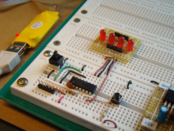
Today’s lab session is about binary counting LEDs. The binary 1 and 0 will be represented by turning LEDs on and off. You will make a 4-bit binary counter (using 4 LEDs) that counts from 0 to 15 (0000-1111 binary). The four LEDs are connected to RC0 through RC3 port pins of PIC16F688 with current limiting resistors (470? each) in series. A push button switch is connected to pin RC4 to provide input for the counter. The counter starts from 0, and increase by 1 every time the button is pressed. When the counter reaches 15 (all LEDs on), it will reset to 0 on the next press of the button.
Required Theory
You should be familiar with the digital I/O ports of PIC16F688 and their direction settings. If you are not, read Digital I/O Ports in PIC16F688. Read previous lab session (Lab 2: Basic digital input and output) to learn about reading inputs from a push button.
Circuit Diagram
The circuit diagram and its construction on the breadboard are shown in figures below. The PIC16F688 microcontroller uses its internal clock at 4.0 MHz.


Software
Define PORTC pins RC0-RC3 as output, and the pin RC4 as an input. Disable comparators (CMCON0=7), and configure all I/O pins as digital (ANSEL=0). Use Button() function to read input from the push button switch.
/*
Lab 3: 4-bit up counter
Internal Clock @ 4MHz, MCLR Enabled, PWRT Enabled, WDT OFF
Copyright @ Rajendra Bhatt
Nov 6, 2010
*/
// Define Tact switch @ RC4
sbit Switch at RC4_bit;
// Define button Switch parameters
#define Switch_Pin 4
#define Switch_Port PORTC
#define Debounce_Time 20 // Switch Debounce time 20ms
unsigned short count;
void main() {
ANSEL = 0b00000000; //All I/O pins are configured as digital
CMCON0 = 0x07 ; // Disbale comparators
TRISC = 0b00010000; // PORTC all output except RC4
TRISA = 0b00001000; // PORTA All Outputs, Except RA3
count = 0;
PORTC = count;
do {
if (Button(&Switch_Port, Switch_Pin, Debounce_Time, 0)) {
if (!Switch) {
count ++;
if (count ==16) count =0;
PORTC = count;
}
while (!Switch); // Wait till the button is released
}
} while(1); // Infinite Loop
}
Output
The counter starts from 0 (all LEDs off), and is incremented by 1 on every button press. After it reaches 15, it overflows and takes the next value 0. This repeats forever.

|
|
Thank you so much Raj! 🙂 again!
It would be great to have others pic experiment now 🙂
all the best!
marC:)
hamza, you can declare a variable count , and count every time the switch debounces
good luck!
marC:)
hello
again here the same problem of button in this as lab 2 digital i/o ports
but the hex code provided works well
is it possible to use oldstate flag in this programme
help
can u write mikroc programe for push button switching programe.
if 1st time push button pressed–>led glows onetime(calling function)
if 2nd time push button pressed–>led glows twotime(by calling another function)
if 3rd time push button pressed–>led glows threetime(by calling another function)
then repeat programe…
my email id:softname@gmail.com
if u post me in my email .it will help better
this is realy work or not?????