Making a simple clap switch
|
|
A clap switch is a fun project for beginners. It switches on and off electrical appliances with a sound of clapping hands. Today we will discuss about making a simple clap switch that operates when it detects two clapping sounds in a row. It uses an electret microphone as a transducer for converting a clapping sound into an electrical signal. The microcphone output is amplified by a transistor and is then sent to the PIC12F683 microcontroller which performs an ON/OFF switching action when valid claps are detected.
Theory
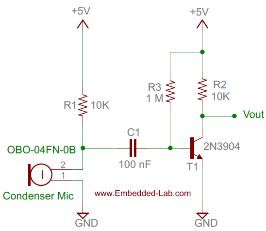
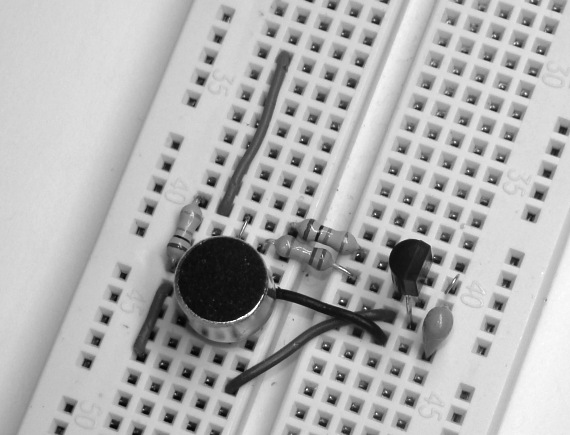
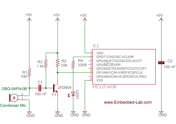
The clap switch requires a transducer at the input to convert sound vibrations from clapping hands into electrical energy. An electret microphone or simply mic (OBO-04FN-0B) is used for this purpose. The output from the mic is very low in magnitide and so we need an amplifier circuit to boost the detected sound signal. The following circuit diagram shows the mic along with a single transistor amplifier. When there’s no sound, the collector voltage (Vout) of the transistor, which is saturated, is approximately 0.2V. When the mic detects a clap sound, the voltage across it drops suddenly. Since the condenser mic’s output voltage is coupled to the base of the transistor through capacitor C1, the base-emitter voltage is also lowered and as such the base-emitter junction is less forward biased or cutoff (in case of high clap sound). Therefore, every time a clapping sound is detected, there is a sudden peak arising at the collector voltage.
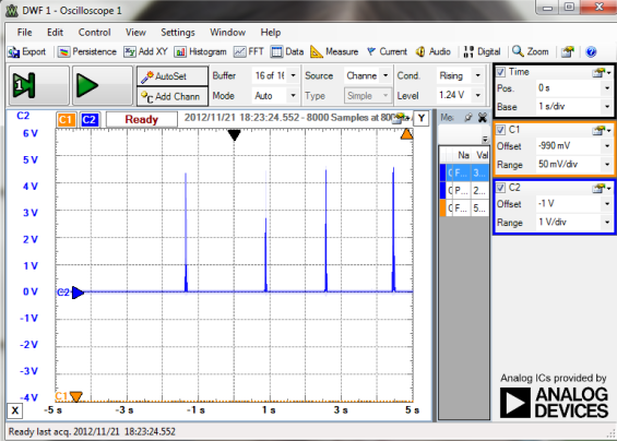
The following picture shows the peaks in the collector voltage due to multiple clap sounds. You can see the peak voltage can go as high as 4.0V depending on the loudness of the clap. This waveform of the collector voltage is captured using Digilent’s Analog Discovery device.
Now we know how to convert a clap sound into an electrical signal. The next stage is to feed this signal to PIC12F683 microcontroller for switching actions. The PIC12F683 microcontroller has got a built-in comparator module that can be used to compare two analog voltages and obtain a digital indication of their relative magnitudes. The comparator module can operate in eight different modes based on CM2-CM0 bit settings in the CMCON0 register. For our purpose, we will configure it as:
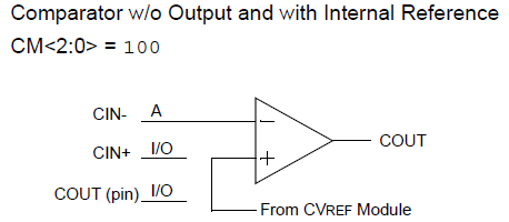
CIN- pin is configured as analog, CIN+ pin is configured as I/O, COUT pin is configured as I/O, Comparator output available internally, CVREF is non-inverting input (see picture below).
We will compare the collector output voltage (Vout) against an internally generated reference voltage. The reference voltage is internally connected to the positive input (CIN+) of the comparator module, while the output voltage from the transducer is fed to the negative input (CIN-) of the comparator. The CIN- pin is multiplexed with GP1 I/O pin of PIC12F683. The magnitude of reference voltage is programmable and controlled through VRCON register. We will set the reference voltage to 0.625V (assuming the supply voltage is 5.0V). So, under normal condition the reference voltage (0.625V) is greater than Vout (=0.2V) and the comparator output (COUT) is high. COUT is accessible internally as well as externally through GP2 I/O pin. When there is a clap sound, COUT will go low. The comparator output logic can be inverted by setting the comparator output inversion (CIN) bit in the CMCON0 register. The PIC12F683 microcontroller can be programmed to take switching actions based on the comparator output.
Circuit diagram
The complete circuit diagram of this simple clap switch project is shown below. The positive and negative inputs of the internal comparator module are externally accessible through GP0/CIN+ and GP1/CIN- pins, respectively. Since, the positive input is connected to the internal reference voltage source, GP1 pin can be used as a I/O pin. The output from the transducer amplifier goes to GP0/CIN+ pin. An LED is connected to GP5 pin to indicate the switching action of the microcontroller. When the microcontroller detects two clapping sound in a row, it toggles the logic output at GP5 pin. The LED is used here for illustrative purpose and it can be replaced with an electromechanical relay if you want to control an electrical appliance with it.
Software
The program is developed in C and compiled with MikroC Pro for PIC compiler. The program continuously looks for two clapping sounds in a row withing 1.5 sec interval. If that happens then GP5 pin is toggled. When a clap is detected, Timer1 module is turned on to keep record of time. It generates a Time Out signal after 1.5 seconds. If there’s no second clap before that, the microcontroller ignores the first clap, and returns to the main program.
/* Project: Making a simple clap switch Description : Clap switch using built-in comparator module of PIC12F683 MCU: PIC12F683 Oscillator: Internal 4.0000 MHz, MCLR Disabled, PWRT ON enabled Written by: Rajendra Bhatt (www.embedded-lab.com) Date: Nov 21, 2012 */ sbit Output_LED at GP5_bit; unsigned short i, TIME_UP; void interrupt(void){ if(PIR1.TMR1IF) { i ++; if(i == 3) TIME_UP = 1; // Time Up in 1.5 sec PIR1.TMR1IF = 0; } } void main() { TRISIO = 0b00000011 ; ANSEL = 0x00; INTCON = 0b11000000 ; // Enable GIE and PEIE for Timer1 overflow interrpt PIE1 = 0b00000001 ; // Enable TMR1IE // Configure Comparator module // CIN- pin is configured as analog, // CIN+ pin is configured as I/O, // COUT pin is configured as I/O, // Comparator output available internally, // CVREF is non-inverting input // CINV is set to 1 CMCON0 = 0b00010100; VRCON = 0b10100011; // Vref is set to VDD/8 Output_LED = 0; do{ TMR1H = 0x00; TMR1L = 0x00; TIME_UP = 0; i = 0; T1CON = 0b00110000; // Configure Timer 1 if(CMCON0.COUT){ // First clap detected Delay_ms(100); T1CON.TMR1ON = 1; // Start Timer1 while(!CMCON0.COUT && !TIME_UP); // Wait until second clap is T1CON.TMR1ON = 0; // detected or Timer1 overflows if(CMCON0.COUT && !TIME_UP) Output_LED = ~Output_LED; Delay_ms(100); } } while(1); } |
Download mikroC source and HEX files
Output
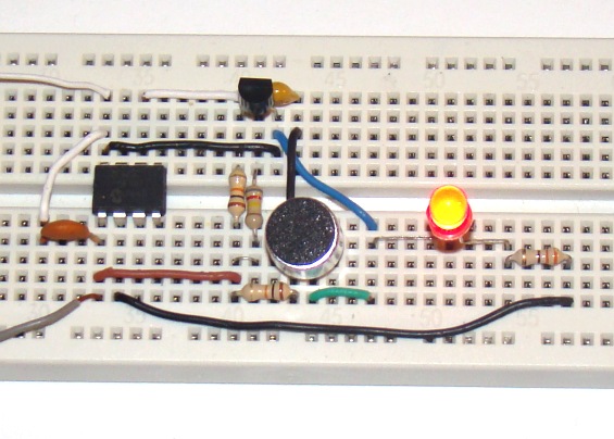
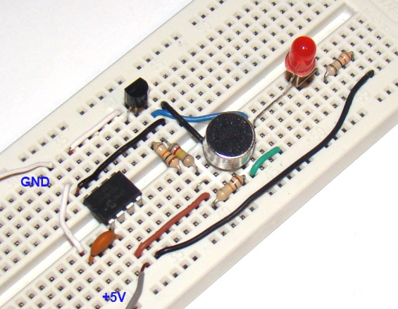
Watch the following video to see the clap switch in action. It has been tested with clapping made at 10 feet away and found operating well.
|
|

The Led keeps blinking, can you help me please ?
When I clap a distance of 5 meters is what the led lights ???????
thank you !
When I clap a distance of 5 meters is what the led lights ???????
thank you 🙂
Hi, When I clap a distance of 5 meters is what the led lights ???????
thank you !
Check out this great clap sensor i found at Pololu: https://www.pololu.com/product/2580
Pingback: World's Top 20 PIC microcontroller projects ideas for enthusiasts
i was try but it not working… how more loud to clap?
instead of LED i want to glow my room light is that possible? and how?
just use more big led using 5volt or use relay can support 230v and connect by your lamp for your room
Pingback: DIY Desk Clock | A BIT of Mystery
guys can you tell me what is that small round(circle) black thing on the left side of the LED in the circuit?
That is the Condenser Mic which is used to pickup the clapping sound.
Hi … can u tel me how to program the pic controller? ?I have bout everything but I Don no how to program pls tel me
Excelente lo hice funcionar pero… como configuro menos time up ?. menos de medio segundo es mucho mejor.
what clap switch project using pic 16f877a possible?,who can help me to modify those codes for being used on PIC16F877A?
This is a good article on clap switch.
There is another well written article ( without programming/micro-controller)
http://rafalerobotics.in/clap-switch/
I tried your circuit but it does not run. Can you give me some advise?
How can the circuit, or code be modified to select the number of clap events to trigger the LED? For example, switch selectable of 1, 2, 3 or 4 events…..
hallo
am clemo,i saw ur clip on youtube about anttiny 85
,i was wondering u may help me out with a project programming using attiny45
i wanna make clap switch
operation=clap twice on clap twice off
Can u help me with code that needed for the project?
hi
i dont have ic so what to do
Hello all, this is really a cool project!
Can anybody help me to do the same project on AVR atmega 16?
Hello everybody,who can help me to modify those codes for being used on PIC16F877A?
Thanks.
Hi to all! can i use PIC12F675 in this project instead of PIC12F683? do i need to change anything in the code? thanks for any info…
hi my name is jaco.
i have a electronic project where im required to build a clap switch using the following componets:
33 k ohm 1/4 W 5%
1 M ohm 1/4 W 5%
5 K 6 ohm 1/4 W 5%
270 ohm 1/4 W 5%
47 k ohm 1/4 W 5%
BC 547
100 uF 16 volt redail
10 uF 16 volt redail
1 uF 16 volt redail
1N4148 diode
5mm LED (red or green)
electret microphone
6 V DC PSU
could yo please explain how to connect the circuit. this is my first time.
thanks.
Jaco
I would appreciate if you did the simulation of this circuit in Proteus, or any other simulator and post it on the site!
Nice project .I´ve donne it with a relay and it works great but the clap sound as to be loud.how can I improve the sensibility.
Hi Raj!
Where did you buy your mic?
thanks!
marC:)
i’m using electrolytic capacitor, RAj. Do you use tantalum so it makes it work?
thank you!
marC:)
the double clap doesnt work with my mic 🙁
dear i am learning c.can you please explain this line “(CMCON0.COUT && !TIME_UP)”.i understand the use of if and while but i am unable to understand what is inside the brackets.specially &&
&& stands for logical AND. So if(CMCON0.COUT && !TIME_UP) means if CMCON0.COUT is 1 and TIME_UP is 0 then do {…}.
Pingback: ??????????? ?? ?????? - Blogelectronics
Hi Raj!
Did you put a jumper between base a emitter?
thank you!
marC:)
why do you set the reference to VDD/8. This is not too low? I have tested your design with a scope and i see with a “clap” 4-5 volts output signal, but the scope triger with 200 mv signal wich correspond to normal speech level in a room .For me the reference must be 3-4 volts to see only the “CLAP”.
thank you
JC
Hi JC,
I think it depends upon the sensitivity of the condenser mic. Mine was not too responsive to normal speech level in room.
Thank you for the reply, greatly appreciated! 🙂
i will let you know how it works
thank you again!
marC:)
why you connect The output from the transducer amplifier to GP0/CIN+
while in the program CIN+ pin is configured as I/O how is it compared according to the comparator[ which compare between the analog input GP1/CIN- and the voltage reference]???????????????????????????????????????????????????????????
?????????????????????????????????????????????????????????????????????
?????????????????????????????????????????????????????????????????????
Hi Ashraf,
You were right. I just corrected the circuit diagram. Thank you for pointing to that.
Electrolytic capacitor would work?
Thanks
Raj, it’s hard to get help here… i am sorry but i ask you several time the question about the microphone that doesnt work, you didnt even respond!!!
thank you!
marC:)
Hi Marc,
There was an error in the circuit diagram before. I have made corrections now. The transistor output should go to GP1 instead of GP0. Try it now.
Raj? Can’t you help me on this?
thank you!
marC:)
The led keep blinking… 🙁
Raj? where did you buy your microphone?
thank you so much!
marC:)
Hi Raj! The led seems to blink all the time?!
thank you for your help!
marC:)
How about a single clap??
thank you!
marC:)
is it possible to connect a relay instead of a led??
thank you!
marC:)
Hi Marc,
Yes, you can connect a relay switch instead of the LED, just as shown in my timer project: http://embedded-lab.com/blog/?p=1378
Is ir possible to add a relay instead of a led??