Netduino Tutorials and Projects
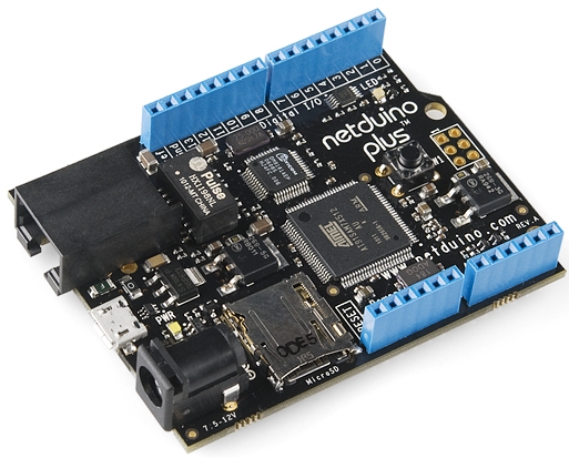
Netduino is an open source embedded systems development platform similar to Arduino, except it uses the .NET Micro Framework for programming. The Netduino development board has the same factor as Arduino Uno, and therefore most of the Arduino shields are also compatible with Netduino. The major difference between the two is the type of processor used in their boards. The Arduino development boards are based on 8-bit Atmel microcontrollers which run at maximum clock speed of 16 MHz . On the other hand, the Netduino hardware uses powerful 32-bit processors (Atmel SAM7x on Netduino, and STMicro STM32F4 in Netduino Plus versions) and runs at a much faster speed (48 MHz to 168 MHz). The following experimental netduino tutorials are aimed to provide a comprehensive introduction to the Netduino platform and ensure that any beginner, student or hobbyist, will quickly be able to start using it for their own embedded projects and designs. Netduino Plus board is used to illustrate the output in these experiments.
Netuidno has gained a lot of popularity not just among the electronics enthusiasts/engineers but also to the programmer as it can be programmed through Microsoft Visual Studio using CSharp.NET or VB.NET language. Here, we have tried to jump start interested people like you. In this section we will learn the basic requirements or the environment required to do any project.
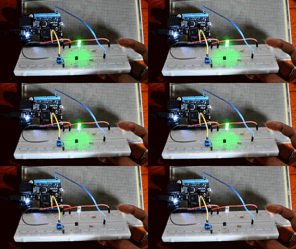
Let’s start with something very simple, by flashing an LED. To make it little more interesting we have added a Potentiometer. Value from potentiometer will change the Flashing rate of a Green LED. To accomplish this, we have used both Digital I/O pins as well as the Analog input pins. A simple program also makes it easy to understand how coding is done to run the Netduino or Netduino Plus.
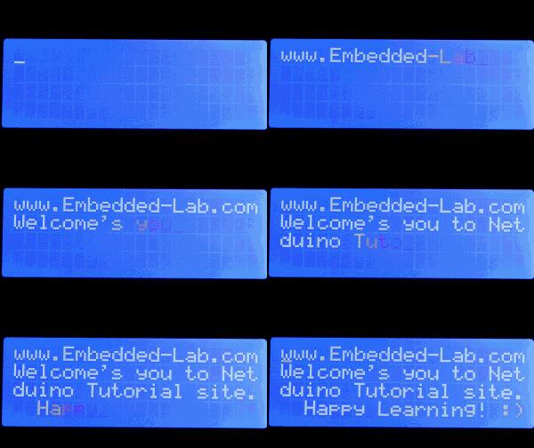
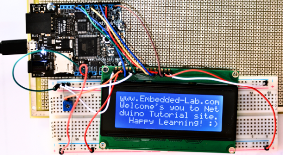
Character LCD are quite powerful at displaying different messages, status, etc and they are equally helpful during debugging too. In this Netduino tutorial, we are using LCD and connecting in a 4 bit data transfer mode. This mode isn’t the fasted but certainly lowers the number of necessary Digital I/O pins
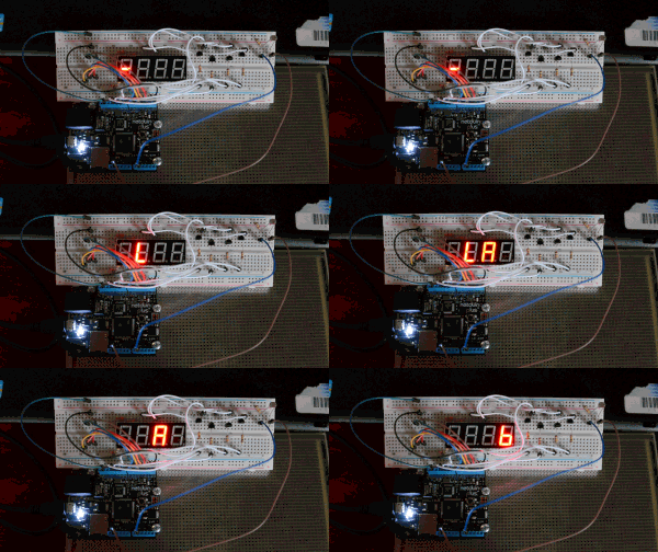
A visual output always adds value to any project. In this third day tutorial, we are going to display some numeric, alphabetic as well as two symbolic characters on a 4-digit seven segment LED module. The way we are interfacing the seven segments LEDs is known as multiplexing, which allows to save some I/O pins of Netduino as compared to driving them individually.
Let’s use the MAX7219 IC to interface 8 digits of Seven Segment LEDs using only 3 I/O pins of Netduino. A custom built MAX7219 class allows you to control all the LED segments in a variety of ways including scrolling and some animating effects.
Expandable memory is always a plus no matter whether it’s a Phone, Camera or a Microcontroller. Even advantageous if we know how to use it. In this fifth day Netduino tutorial, we will learn a few writing operations about an SD card. We will learn how to write to a text file, shown as an example of writing a log. The Logger class is also capable of creating a text file at any given location then writing some text information to it.
To read SD Card information, we need to take it out from Netduino board and plug it into computer and doing that couple of time, you wonder there gotta be better way and hence this tutorial comes in play. We will read SD card information (that was written in earler tutorial) in this tutorial using Serail Communication.
Pulse Width Modulation (PWM) is a digital method of delivering a varying amount of power to a load, and hence can be used to control the brightness of an LED or speed of a DC motor. Controlling the power, we will make this tutorial colorful using a Red Green Blue (RGB) LED. Each segment (lead) of an RGB-LED will get a PWM signal via RgbLed class allowing us to illuminate the RGB-LED with any color defined by RGB.

