AVR displays body temperature on a Nokia 3310 LCD

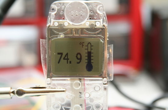
This project describes how to measure temperature with Atmega8 and a thermistor and display it on a Nokia 3310 LCD. A thermistor is a device that changes its resistance with temperature. With a proper resistor divider network, the temperature can be measured by measuring the voltage across the thermistor. The voltage across the thermistor is measured by the on-chip ADC of Atmega8. The necessary coefficients to convert the resistance to temperature are given in the manufacturer’s datasheet of the thermistor. The thermistor used in this project is Vishay NTCLE100E3103JB0 (found at Sparkfun.com).

Read more

Lab 1: Flashing an LED

Description Today is our first session in PIC microcontroller lab, and we will begin with an experiment that flashes an LED on and off. While this looks very simple it is the best project to start because this makes sure that we successfully wrote the program, compiled it, loaded inside the PIC, and the circuit is correctly built on the breadboard. In this lab session we will connect an LED to one of the port pin of PIC16F688 and flash it continuously with 1 sec duration. Required Theory You must be  familiarized with, digital I/O ports (PORTA and PORTC) of PIC16F688

Read more

Digital I/O Ports in PIC16F688

PIC16F688 is a 14-pin flash-based, 8-bit microcontroller. It can be obtained in different packages, but the DIP (Dual In-line Package) version is recommended for prototyping. The figure below shows a PIC16F688 microcontroller in DIP chip, and its pin outs. Most of the pins are for input and output, and are arranged as PORTA (6) and PORTC (6), giving a total of 12 I/O pins.  All of these can operate as simple digital I/O pins but they do have more than one function. For example, eight of total 12 I/O pins also serve as analogue inputs for the internal analog-to-digital converter

Read more

Hardware and Software requirements

The development of an embedded system requires some hardware and software products. Although the hardware requirements depend on the type and complexity of the project, the following hardware tools are required in all of the experiments we are going to discuss here. A solderless breadboard for constructing and testing the experimental circuits. The breadboard is chosen because it is reusable. You can change, modify or remove the components on it at any time. While an embedded system is in development phase, you never know in advance whether or not your circuit will function correctly when assembled. So it is always good to

Read more

Lab 2: Basic digital input and output

Description Today we will learn how to read digital inputs from a push button switch. A digital input has only two values: 1 and 0. The configuration of the push button switch is same as that of the reset switch except it goes to a different port pin. The status of the switch will be read through RC1 and every time when it is pressed, an LED connected to RC0 will be toggled ON and OFF. Required Theory You must be familiar with the digital I/O ports of PIC16F688 and their direction settings. If you are not, read Digital I/O

Read more
« Older Entries Recent Entries »