Portable Bluetooth-enabled scrolling LED matrix display- Part 1
|
|
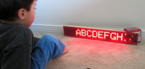
LED matrix displays are great fun. They are visually charming, and readable from a far viewing distance with a much wider angle of view as compared to many other types of electronics displays. They can display all kinds of information, including text, graphics, and animation. This project is about making a portable Bluetooth-controlled 8×64 monochromatic LED matrix (total 512 LEDs) for displaying scrolling text message. I made this display to use at home parties or other occasions for displaying greeting messages. The text data to be displayed can be sent from a smartphone using the Bluetooth connection. The display is Arduino-controlled and uses the HC-06 Slave Bluetooth transceiver module for receiving data from the smartphone. I am also using the Bluetooth SPP Pro (freely downloadable) App (developed by Jerry.Li) on my HTC One Android smartphone for sending text message to the matrix display. The complete project has got a nice enclosure made by myself using furring strip boards bought from the Home Depot. We looked at a similar project earlier made by Jollyfactory, who used bi-color LED matrices, which required two MAX7219 devices per 8×8 matrix.
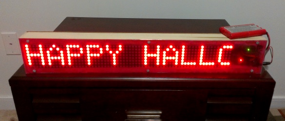
Bluetooth-enabled scrolling LED matrix display
Hardware design
This project uses eight pieces of 60.5mm x 60.5mm (2.4″ x 2.4″) monochromatic 8×8 LED matrix modules with A-type polarity, which means the rows are common-anodes and the columns are common-cathodes. The total size of the display area thus becomes about 2.4″ x 19″ (60.5mm x 483mm). Making one big piece of PCB of that size usually costs more than making small and cascadable modules. So I designed 8×8 LED matrix modules and daisy-chained eight of them to make the 8 rows x 64 columns matrix required for this project. Each module consists of an 8×8 monochromatic LED dot matrix display with onboard MAX7219 driver chip. I have named this module Easy Matrix. It consists of a 5-pin angled male header (J1) on the right side and a 5-pin angled female header (J2) on the left side of the board. Both the headers are precisely aligned along horizontal so that the male header of one module gets easily plugged onto the female header of second module, and so on. Two 1×8 straight female headers are used as sockets to hold the LED matrix module. One of the header socket is marked with a “circle with 1” to indicate where the pin number 1 of the LED matrix display should be inserted. Four 3.5 mm mounting holes are also available at four corners of the PCB. The MAX7219 data and control signals are fed from the J1 header of the first module (the right-most module) in the chain. The complete schematic and board files can be downloaded from a link provided at the end of this section. Here are some pictures of an Easy Matrix module below.
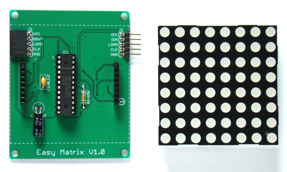
Easy Matrix module
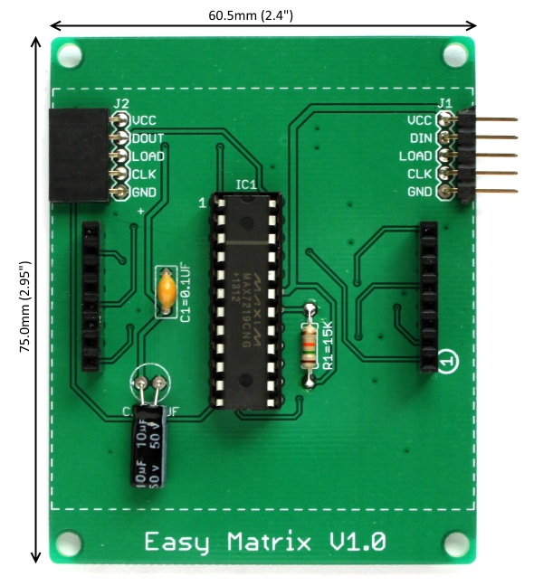
Dimensions of Easy Matrix board
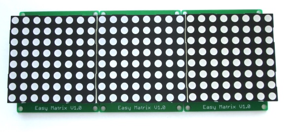
Daisy-chaining three Easy Matrix modules
Features
- Operates at +5V
- 16 brightness levels controlled through software
- Easily cascadable (recommended maximum 8 modules in a cascade)
- Supports both Mark Ruys’ Max72xxPanel (Adafruit’s GFX library is also required) and MaxMatrix libraries.
Download Eagle Design files
If you are interested in getting all the parts for making Easy Matrix modules, look for their kits at my Tindie store.
Arduino connections
Eight Easy Matrix modules are cascaded to construct the 8×64 matrix display, which requires only three I/O pins of Arduino to drive the data and signal lines. In this project, we will be using the hardware SPI module of Arduino to drive the Data and CLK signal lines of MAX7219. So, the MOSI (digital pin 11) and SCK (digital pin 13) pins of Arduino Uno are connected to the DATA and CLK pins of the J1 header (in the right-most Easy Matrix module), respectively. The LOAD pin can be driven with any arbitrary I/O pin. We connect the Arduino digital I/O pin 10 (defined as pinCS in the code below) to the LOAD pin. Besides, a 1K resistor is also required in this project, which is connected in between Arduino pins 0 (RX) and 2 (External Interrupt). This configuration generates an external hardware interrupt upon the arrival of any new serial data, and Arduino responds to it by immediately reading the data. This is important to prevent the overflow of data in the UART serial receive buffer, which has a capacity of storing only 64 bytes.
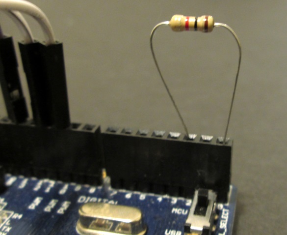
Connecting a resistor between the RX (Pin 0) and Interrupt pin (Pin 2)
The cascade of 8 Easy Matrix modules requires approximately 1Amp of current for full brightness. The 5V regulator on Arduino Uno board cannot provide this much amount of current. So an external +5V power supply is needed. We will discuss about this in more detail later. For now, let’s use a cascade of five Easy Matrix for developing and testing the Arduino firmware. This can be powered directly from the Arduino board 5V supply. We will first test the firmware directly from the Serial Monitor terminal window by connecting the Arduino to PC through USB-UART bridge. Later we will replace the USB-UART bridge with a serial Bluetooth adapter.
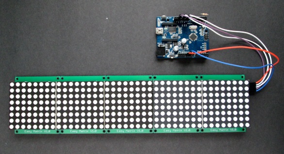
Complete test setup of the project
Arduino Firmware
Mark Ruys’ Max72xxPanel and Adafruit’s GFX libraries are required for this project. So install these libraries into your Arduino libraries directory, if you have not done it already. You can download the complete Arduino sketch that I have developed for this project from the link provided at the end of this section. The Arduino receives the display data and other commands, like scrolling speed control and brightness adjustment, through its serial port at 9600 baud rate. The text message to be displayed is sent by enclosing it inside a open and a closed parenthesis, whereas commands are sent by starting with a ‘/’ character. Here is a list of the commands implemented in the firmware.
- (message) – The scrolling display message must be sent enclosed by parenthesis.
- /p to pause the scroll. Sending it again resumes the scroll.
- /< to scroll faster
- /> to scroll slower
- /+ to increase brightness level
- /- to decrease brightness level
- /e to erase the display
When we send data to Arduino through the serial port, it gets interrupted to respond to this event. It first reads the first character to recognize if the upcoming data is a string of text message (if the first character was ‘(‘) or command (if the first character was ‘/‘), and act accordingly. Note that if the text scrolling is paused and a new display message is sent, it won’t show up on the display until the scrolling feature is resumed by sending ‘/p‘. The maximum buffer size defined for storing the incoming text message is 512 bytes (which is 512 characters).
Download Arduino sketch
(Note: You need to install the Mark Ruys’ Max72xxPanel and Adafruit’s GFX libraries first)
Demonstration
As I mentioned above, we will test the firmware first using the USB-UART connection between Arduino and PC, and later will replace the link with a Bluetooth adapter. For quick testing, I am using only five Easy Matrix modules (i.e. 8×40 LED matrix). For this, connect the Arduino board to USB port of the PCB and upload the Arduino sketch. Once the upload is completed, open the Serial Monitor program. Set the baud rate to 9600. Then type in the string (HELLO) and hit the Send button. The Arduino receives the character string and displays it on the LED matrix scrolling from right to left.
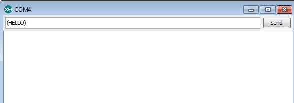
Sending text message from the Serial Monitor application
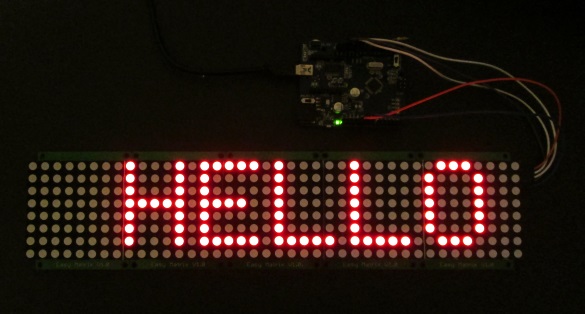
Test output on LED matrix
The following video illustrates the execution of other commands that were discussed earlier in the software section. Note that these commands begin with the character ‘/’.
In the second part of this article, we will continue this project by cascading 8 Easy Matrix modules and making an external +5V supply with higher current rating to power the display. We will also discuss about implementing a Bluetooth adapter in the project for wireless transmission of text messages to the display through the Bluetooth SPP Pro App running on an Android phone.
Continue to second part …
|
|
hello sir,
i just want to interface lm35 or dht11 sensor with led display using aurdino.can you just help me out from this.the display should be scrolling.
will be waiting for your replay.
rahulmishra6412@gmail.com
Hi! You helped me a lot, I was studying Arduino and your project made me learn many things, THANK YOU SO MUCH
Will you please send me the CODE for this program without Bluettoth module ?
Pingback: ESP8266 Wifi enabled 8×64 pixel LED matrix display - Electronics-Lab
hello friends someone already can save the messages in the eeprom ?
Hi Sir !
Does the Led Matrix still running when we’re disconnected the bluetooth…..
good day sir, please i need your help on moving massage display based on gsm sms, i need the circuit diagram and code in c and hex file, sir will be happy if u help me, this my email chekwubemartins@yahoo.com.
Does yor sketch work with a cascade of 5 led matrixes?
I worked with 7 matrix, so far so good.
Does yor sketch work with
Let me tell you Raj that your code is really fantastic, because Iam looking for months how to work with MAX7219 and using BT with a smartphone, so your idea is very usefull, thanks a lot for sharing and now I can do some projects for my Church by using biblical messages in classroom, certainly a few parts of your code I can’t figure out but it works 150%. Iam a beginner of Arduino and this portable scroll matrix has a many benefits.
Can you pls send me the codes.. l can’t able to download from hare. My email is ayan.s73558@gmail.com
I am trying to do this project using ChipKit UNO 32, But every time I send a message to the Matrix LEDs nothing display. I tested with arduino and it works perfectly using the same codes and connections. Can anyone help me to make it work with ChipKit UNO 32?
How would I get this to function without inverting every other display? If possible could you produce an arduino sketch for it?
Very nice! I have elderly parents and would love to design a Bluetooth-enabled marquee display directly from phone text. Give them notifications that are head-turning. 🙂
Thanks.
See amazing LED project here: http://kck.st/1Oi2sHC
Simply and affordable…
can we use arduino uno instead of nano?
Sir will u please tell me , how to cascade 16 module of 8*8 matrix module…
Pingback: Wyświetlacz 8x8 z kontrolerem MAX7219 wyświetlający polskie znaki » Majsterkowo.pl
and again,can any bluetooth shield work,sir?
can one use 595 like in the pic project?it seems simpler since the maxim chip is not found everywhere!
hi, my real name is stephen gachara, I am working on quite a similar project, only that I am using the sim 900/1800 quadband gps/gprs arduino shield to send send text to the arduino and finaly to the board, the gsm shield receives texts from the normal mobile phone… please help me on coding …
hi, my real name is stephen gachara, I am working on quite a similar project, only that I am using the sim 900/1800 quadband gps/gprs arduino shield to send send text to the arduino and finaly to the board, the gsm shield receives texts from the normal mobile phone… please help on coding …
Pls Sir, Help me Sir I need your Assistance with the Complete Code/Arduino Sketch
My Email; n.ezechukwu@yahoomail.com, nezechukwu@namahqtr.net
Download link is provided in the article. Or use this:
http://embedded-lab.com/blog/wp-content/uploads/2014/10/Easy_Matrix_Demo1_Scrolling_Message_UART_With_Interrupt_on_Pin2.zip
Hello there
I have tried your circuit for cascading LED Matrix. It is working but I have some troubles trying to save it into the EEPROM and reading it back so that once the device is switched off and back on again, the data displays automatically on the LED Matrix again.
It is sucesfully stored into the EEPROM and saved bit by bit into the address, I just need to re initialize it.
Could you please have a look in helping me if possible? I would appreciate it very much.
The link to the modified code is as follows:
http://forum.arduino.cc/index.php?action=profile;area=showposts;u=361498
or
http://forum.allaboutcircuits.com/threads/arduino-led-matrix-eeprom.110071/
Thank you in advance!
hello friend you already can save the messages in the eeprom ?
Hi Sir!
I live in the country of Vietnam Saigon
I am glad to see the last post “Portable Bluetooth-enabled scrolling LED matrix display- Part 1”.
at the web address: http://embedded-lab.com/blog/?p=9255.
I really thank you for writing a very detailed and careful.
By the way I would like to donate to the drawing board electronic “Easy Matrix v1.3” with the lines a little bigger circuits that board size has not changed ..
Let me ask a little if you want to send attachments me how?
I sent the file to sir with my Gmail address to the address admin@embedded-lad.com but no response.
Excuse me for disturbing gentleman.
Hello goodbye see you soon!
Pingback: Embedded Lab wishes you a very happy new year - Arduino collector blog
Hello!
I tried using the Demo code on Common Anode matrix arrangement, but it seems not to work at all, please can you suggest any reason why its not working?
Thanks