Portable Bluetooth-enabled scrolling LED matrix display- Part 2
|
|
In Part 1 of this project, we described the construction of Easy Matrix, which is a cascadable 8×8 LED matrix display with MAX7219 chip on board. We developed an Arduino sketch for scrolling text display, whereby the Arduino receives text messages from its serial port and displays the message on a 8×40 LED matrix constructed by daisy-chaining five Easy Matrix modules. The Arduino firmware is also capable of receiving user commands for controlling the scrolling speed and brightness level of the display. In this part, we will discuss about extending the project to cascade 8 Easy Matrix modules and control the display over a Bluetooth connection.
Power supply and display driver circuits
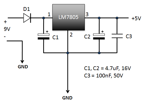
The 8×84 LED matrix is powered using a LM7805-based 5V regulator circuit with 1.0 Amp current capacity. For the input supply, I am using a 9.6V rechargeable battery pack. A DC wall adapter can also be used as long as it is rated 1.0 Amp or higher. The power supply circuit is very simple and shown below.
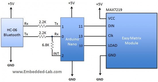
For the control circuit, I am using Arduino Nano version because of its smaller size. The following diagram shows the connections between the HC-06 Bluetooth module, Arduino Nano, and the LED matrix display. The HC-06 module used in this project is the one with on-board regulator for 3.3V supply. It acts as a bridge between the Arduino serial port and the Bluetooth port on your smartphone. The UART Rx and Tx pins of HC-06 and Arduino are cross-connected through two 2.2K resistors. These resistors allows to update Arduino firmware without disconnecting the HC-06 module. A 6.8K resistor is used to connect the interrupt pin (2) and the Rx pin of Arduino. The Arduino digital pins 11, 13, and 10 are used to drive the input signal lines DIN, Clk, and LOAD, respectively of the MAX7219 chip on the right-most Easy Matrix module in the daisy-chain.
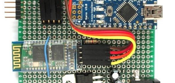
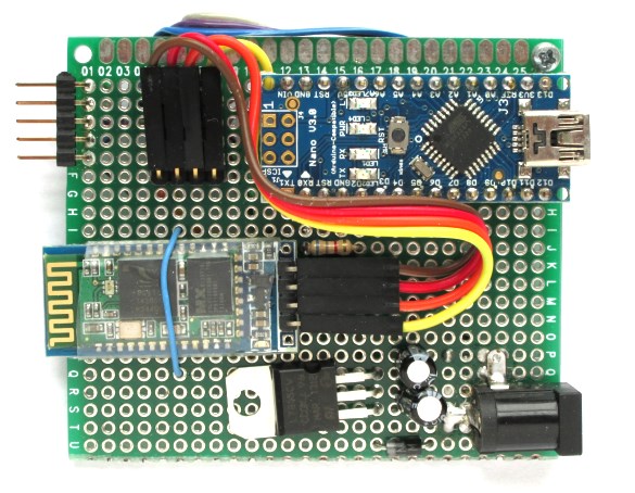
The following picture shows a complete setup of the power supply and control circuit. Note the male headers shown on left connect to the MAX7219 signal and power lines of the Easy Matrix module.
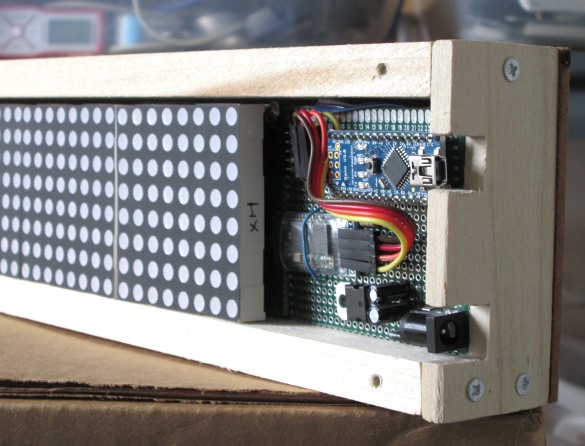
The cascade of 8 Easy Matrix modules along with the Arduino control circuit are enclosed into a customized box made out of furring strip boards from the Home Depot. Two square cuts are made on one side to access to the power supply jack and USB connector.

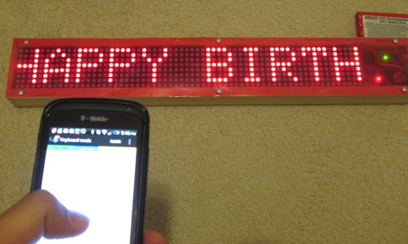
The front side is covered with a transparent red plastic to enhance the visibility of the red LED pixels
Bluetooth SPP Pro App
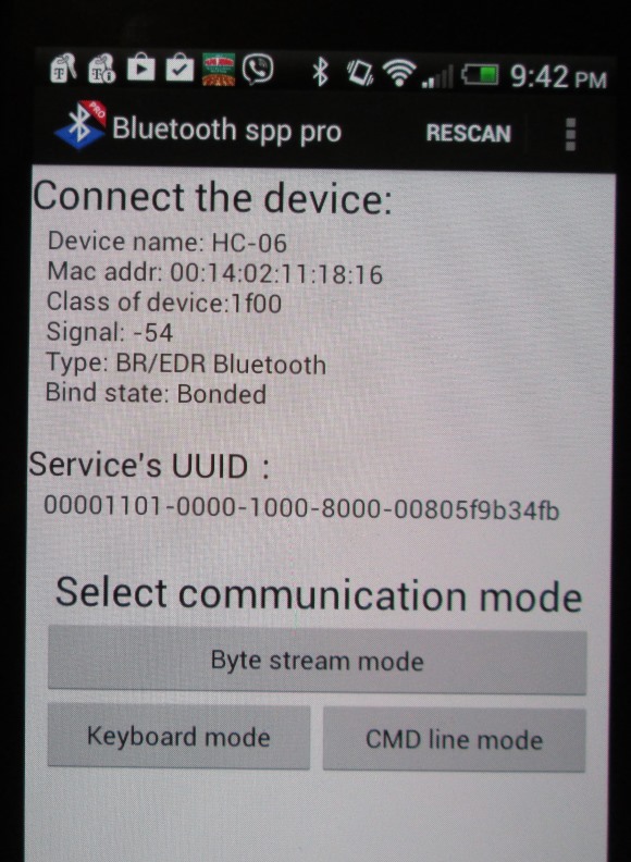
In this section, we will briefly discuss about the Bluetooth SPP Pro App and its setting to meet the requirements of this project. It is a Bluetooth client communication tool developed by Jerry.Li for Android platform and it allows to transfer data from your smartphone to the HC-06 module in ASCII or HEX format. The App searches for surrounding Bluetooth devices and displays their class and RSSI information. Once connected to the HC-06 module, the main menu shows three data transfer options, namely Byte Stream, Keyboard, and Command line mode. The Command Line mode can be used to send the display data and commands to the LED matrix just like we did in Part 1 using the Arduino Serial Monitor. It could be little tedious to type in the characters on smartphone compared to using the PC keyboard. On the other hand, the Bluetooth SPP Pro App provides 12 touchscreen buttons in Keyboard mode, where the outputs of button presses can be easily customized. This mode is useful to store text messages and send them whenever you want by simply touching the buttons. I will show the demo of it here.
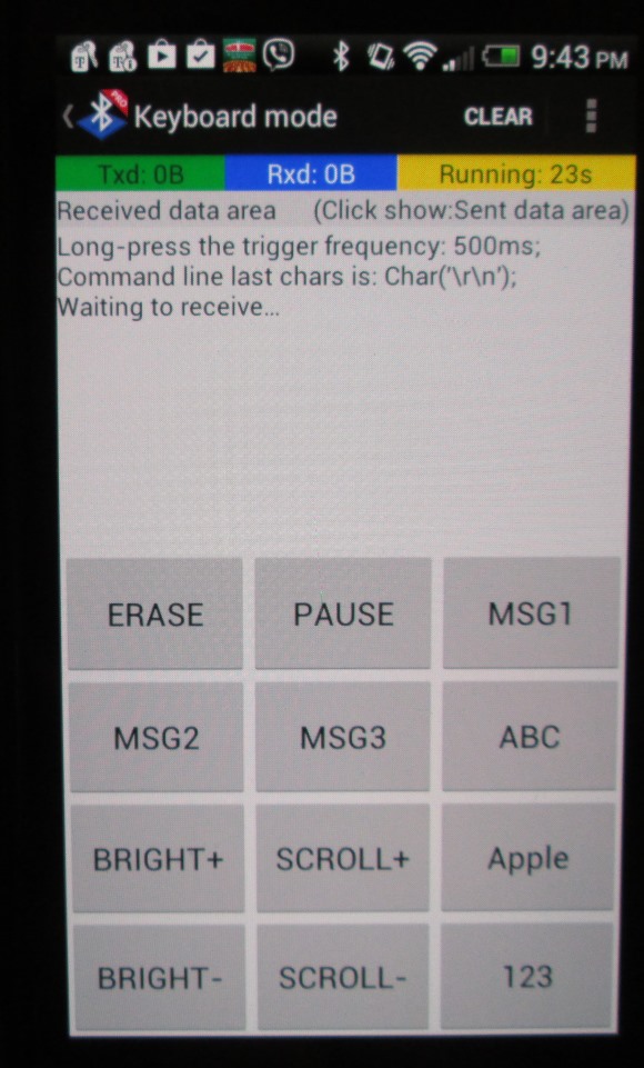
The picture below shows the 12 press buttons on screen that I have customized for this project. Six buttons are customized for the control commands we have implemented in the Arduino firmware, which are Brightness level up and down, Scrolling speed high and low, Pause, and Erase. Other buttons are used to store text messages.
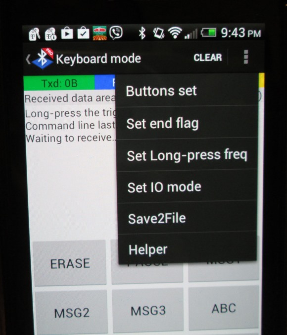
The customization is very easy. First you need to select the Button set option from the option menu on top right.
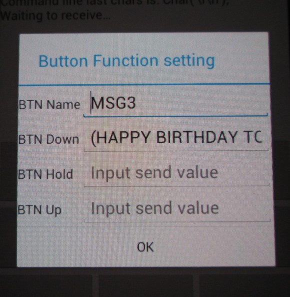
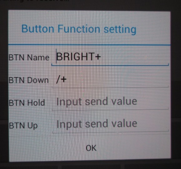
And then select which button you want to customize. A Button Function setting window shows up, where you can set the name of the button and the output data that you would like to send to the Bluetooth slave (HC-06 in this case) device when it is pressed. Remember that if you want to send a text message for display, it has to be enclosed inside two parenthesis as we discussed in Part 1.
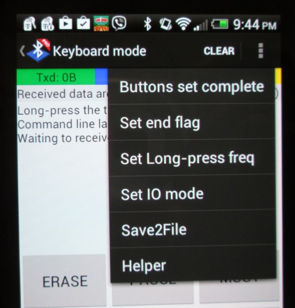
Once you are done with all your button settings, you can go back to operation mode by selecting Buttons set complete option from the main menu.
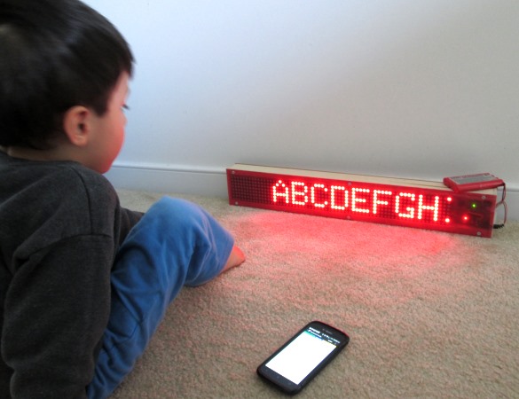
And here is a video of the display in action.
Easy Matrix kits are now available on my Tindie store.
Buy Easy Matrix kit here!
|
|

Please send the code
Dear sir
Great project ….
how would he show an opening sentence message as soon as the arduino is switched on?
Excellent project …
Is it possible for him to present an initial message when the arduino is connected?
Please send me all codeof the project in my email address rohitpol1258@gmail.com
Sir, Thank You For This Wonderful and Outstanding Project. I will be Most Grateful if You can Send me the Complete Codes/sketch for Your Project.
My Email: elrifo.s2s@gmail.com
thanks very much
Can you pls send me the codes
Hello sir
please code Thanks
Hello Sir
can you please provide me with the code
Thanks and regards
Hello Sir
can you please provide me the code of this project silverlinejsr@gmail.com
Thank You
Excelente proyecto, me funcionó al 100%. Gracias!
Hello!
Great project,
I’m working on a similar one in my university (with DMD) , so i will be great-full if you give me the (.aia) of the Android application you used so i can modify on it, cause i want to add a lot of things instead of the exist ones,
Best regards.
Abderrahman
I wonder, can this hardware (LED matrix board with serial input) be used to receive serial information from PC program “LCD Smartie” (choosing Matrix Orbital Serial output plugin)? I am in a search of PC programs that could send to MAX7219 LED matrixes various useful info, say, clock, CPU load, CPU temperature, playing song name and artist, audio spectrum, etc, etc. Software “LCDsmartie” does all that, but will it work with this hardware project? I guess I will try when my LED modules arrives from China. Any thought from Author maybe? Thanks in advance!
I briefly got part one to work. I seem to have bad jumpers. What I seem to have now is lag. Memory issues
I cant get anything to work. I have tried several scrolling max7219 sketches. This would be great for me. I copied part 1 but I cant get the matrices to even light or I got one line lit. It uploads fine. Any possible ideas what could be wrong?
Hi,
I’m on a 24 rows and 51 columns LED bluetooth scrolling,
Can you help me by sending me your code.
I have this working perfectly. I have been fiddling around for almost a week trying to make the message non-volatile. EEPROM library with write after the (xxxx) cr. then after power out, read EEPROM to display until the next interrupt sets new data. ideas?
dave
hi
can you please tell me if same code works with bluetooth or not ,
if yes can you please tell me how.
do i need to use nano for second part.
followed your steps exactly but not working when connecting bluetooth.
thanks
Hello very good project
see who has extensive experience in MAX7219 matrix screens, you will have a version that integrates an RTC DS1307 and DHT11 to your project.
how can I make HC-05 Bluetooth to work with your project?
TIA
Sir, Thank You For This Wonderful and Outstanding Project. I will be Most Grateful if You can Send me the Complete Codes/sketch for Your Project.
My Email: n.ezechukwu@yahoo.com.
May God Bless You Sir.
Hi! First of all great project but I have to point 3 mistakes, a) matrix is common cathode and not common anode look for codes of matrix with A like 2088(A)S or 2388(A)S and not with B because B is common anode and it won’t work (example 2388(B)S won’t work). b) in code Load is connected to pin10 and not pin 9, so pin 10 is the right! and lastly, bluetooth connection must have a voltage divider, so arduino (RX pin) > bluetooth (TX pin), arduino (RX pin) > 1K Resistor > Digital pin2 of arduino (this is for the delay). Arduino (TX pin) > 1K Resistor > bluetooth (RX pin) > Ground (this is the voltage divider) you can put any resistor you like as long as you provide 3.3 Volts to pin and not 5! I Hope this helps someone else cause it took lots of time to find out why it didn’t work, thanks for the useful information though.
Hi, can you please give me your mail, i have started with tis project, and i see that you have experience with it, so i can ask for help when i get stuck. Thanks 🙂
Fotiou5@yahoo.gr my friend, I’ll do my best because I am a hobbyist not professional
Is this working with Arduino UNO?
Finally. Its working now. Thanks
Hi Kostas Fotiou.
I used a single 3K3 resistor between the Bluetooth Rx pins and the Arduino Tx; It’s wrong?
I do not understand why 2 resistors.
Hi, does the program from part 1 cover the use of Bluetooth in part 2 of this project or is there another program? I can get part 1 working but am having difficulty with part 2. Thanks.
It is the same program.
HI !
can you please tell me how to write coding in arduino for this project…? or where can i get ?
thank in advance..
i’m not so expert in electronics..
i just need the bt controlled led matrix display…
is it possible to buy it one already assembled?
let me know!
regards
Leonardo
seguro que esto funciona