Proper PCB grounding for mixed-signal designs

|
|
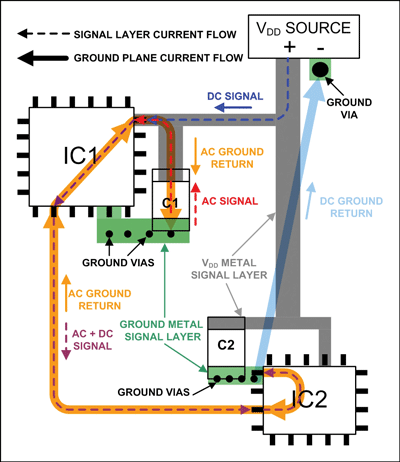
Circuit board designers have always concerns about the proper way to handle grounding for integrated circuits (ICs), which have separate analog and digital grounds. This tutorial from MAXIM integrated discusses proper printed-circuit board (PCB) grounding for mixed-signal designs. For most applications a simple method without cuts in the ground plane allows for successful PCB layouts with this kind of IC. Next, we learn how to place components and route signal traces to minimize problems with crosstalk. Finally we move on to consider power supply-currents and end by discussing how to extend what we have learned to circuits with multiple mixed-signal ICs.
|
|

I am glad you liked the article. I hope it helps a few hobbyists and up-and-coming electrical engineers avoid some common pitfalls in PCB layout. I am glad to see this stuff being exposed at a teaching site.
Hi Mark,
I have always enjoyed reading your tutorials posted on MAXIM’s website.