Running message display project for Christmas
|
|
Introduction
As Christmas is coming people have already lightened their houses. I thought of doing something different for this Christmas besides the festive Christmas lights. I made a running message display using LEDs, and thought of sharing it with you. This is a very simple running message display project that displays the message ‘MERRY XMAS’, where each letter is created with 5mm diameter red-color LEDs. The 9 letters in the message are individually turned on or off through a PIC16F688 microcontroller’s I/O pins. Therefore, a variety of display patterns can be generated through the software inside the microcontroller.

Christmas running message display
Theory
LED Math
The forward voltage of an LED depends on its type. If the LED is red, the forward voltage is usually between 1.7 – 2.1 V. For green and blue LEDs, this value is higher. An LED requires a resistor in series to limit the current in the LED to a safe value. Most 5mm LEDs operate close to their peak brightness at a drive current of 20 mA. In this project, I am driving my LEDs at 15 mA and they still glow pretty bright. So, all of my calculations are based for 15 mA current through the LEDs. I measured the forward voltage across my LEDs and they are about 1.95 V. Calculating the value of the series resistor for an LED is simple. Suppose, if you want to drive a LED through a 5 V power source, you need a resistor of value (5-1.95)V/15 mA = 203 ? to limit the current to 15 mA. The closest available resistor (on the higher end) is of 220 ?.
Now, let’s see how to make display letters with LEDs. The first letter of the message (MERRY XMAS) is shown below. 17 LEDs are used in creating the letter M. If you drive each LED through a 5V supply, you require 17 series resistors, and the current will sum up to 17×15 = 255 mA. If you add the current requirements of other letters in the message, the net current would go up to 2 A, which is quite a bit of current and you probably need a bigger heat sink for your voltage regulator. I didn’t want to do any of these. So I thought of doing it differently that would save me from soldering to many resistors and also lower the net current requirement of the project. How can I do that? Yes, you are right, by using higher supply voltage.

I still have my old printer’s external power supply that has that has 3 output pins for +15 V, +32 V, and Ground, and it can deliver current up to 800 mA. I thought of connecting LEDs in series and drive them through 32 V. This way I can connect at most 16 LEDs in series with only one current limiting resistor. So, here is how I arranged the 17 LEDs for the letter M. I can’t connect all of them in series as that would require more than 17×1.95 = 33.15V. So I connected the first 9 LEDs in series (cathode of one is connected to the anode of other) to form a chain. The remaining 8 LEDs are used to form another chain. For the first chain, the value of the series resistor would be,
R1 = (32.0 – 1.95 x 9) V/15 mA = 963 ?.
I used 1 K. Similarly, for the other chain of 8 LEDs, the estimated resistor value is R2 = 1.1 K. Now let’s compute the power dissipation in the resistors. The current through R1 is (32 – 1.95 x 9)V/1K = 14.45 mA. The power dissipation is 14.45 mA x 14.45 mA x 1000 ? = 0.21 Watts. Similarly, R2 will dissipate 0.24 Watts. So, the resistors with power rating 1/4 Watts will work fine. Next, by connecting the two anode terminals together and two cathodes together as shown above, completes the letter M. The anode terminal will be connected to 32 V supply and the cathode will be connected to the collector of a NPN transistor. The base of the NPN transistor will be driven through a PIC16F688 I/O pin with a base-current limiting resistor, whereas the emitter will be grounded. When the PIC16F688 I/O pin outputs logic high, the transistor is turned on and all the LEDs will glow and display M. This whole process is repeated for other letters in the message. The series resistor values will be calculated in exactly the same way by considering the number of LEDs in each of the chains formed. The table below shows the number of LEDs in my message letters with the number of chains and the series resistors I used.

Selecting transistor
Each transistor used in this project will have to sink at most 30 mA current (for letters with two series chains). If there is only one chain of LEDs, then it would have to sink only 15 mA. So, no special power transistor is required. But, the selected transistor must have junction breakdown voltage higher than 32 V, for both collector-emitter and collector-base terminals. The specification of a BC547 NPN transistor says the breakdown voltage is about 45 V, and so it is appropriate for this project. But I experienced problem with a couple of BC547 transistors that I had to replace. They just get turned on by default without applying any voltage to its base resistor. I don’t know the cause.
Soldering LEDs on a cardboard
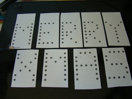
I didn’t solder the LEDs on a prototyping circuit board to make the letters, that would be a lot of money. I rather took a 0.25″ cardboard and drilled holes where the legs of LEDs are inserted. The legs are bent on the backside of the cardboard and then soldered to form a chain of LEDs. This holds the LEDs fairly tight. In order to drill the equidistant holes, first I printed the letters with round circles on papers and sticked them on the board as shown below. The circles are 0.5″ apart.

Next, I drilled two holes inside each circle at about 4 mm distance apart so that I can insert the two legs of an LED. It’s a cardboard, so drilling was not so painful. It took me about 30 minutes to drill holes for all 134 LEDs.

After that, I took the paper out from the cardboard and inserted the LEDs. I bent the legs of the LEDs and soldered the appropriate terminals of adjacent LEDs to make the serial chains. I also soldered the resistors to each anode terminals of the chains.

Circuit Diagram
The circuit diagram is very simple. I am using my PIC16F688 breadboard module as the brain of this project. The figure below shows the pin RC0 is driving the first letter M. Rest of the letters also require similar transistor drivers that are controlled through other port pins of PIC16F688. The +5 V supply for the PIC microcontroller is derived from the +15 V power supply (note the printer power supply has two voltage output, +15 V and 32 V) using an LM7805 regulator IC.


PIC16F688 breadboard module inserted into the transistor driver board. The board gets +15 V and +32 V from the printer’s power supply.

PIC16F688 module controls the switching patterns of the letters

The circuit board is fixed on the backside of the cardboard using screws.
Software
Now it’s time to write the program for PIC16F688. I am demonstrating a simple display pattern that first switches all the letters on sequentially, then blinks the whole message twice, and finally shows the entire message for 2 sec. Then it repeats the sequence for ever. I wrote this program in C and compiled with MikroC Pro for PIC compiler from MikroElektronika.
/*
Project: Merry XMAS Running Message
Internal Clock @ 4MHz, MCLR Enabled, PWRT Enabled, WDT OFF
Copyright @ Rajendra Bhatt
Dec 4, 2010
*/
// Define letter connections.
// MERRY XMAS
sbit M1 at RC0_bit;
sbit E1 at RC1_bit;
sbit RR1 at RC2_bit;
sbit RR2 at RC3_bit;
sbit Y1 at RC4_bit;
sbit X1 at RC5_bit;
sbit M2 at RA2_bit;
sbit A1 at RA1_bit;
sbit S1 at RA0_bit;
// End connection definition
void GetDelay(void){
Delay_ms(200);
}
void main() {
ANSEL = 0b00000000; //All I/O pins are configured as digital
CMCON0 = 0x07 ; // Disbale comparators
TRISC = 0b00000000; // PORTC All Outputs
TRISA = 0b00000000; // PORTA All Outputs, Except RA3
PORTA = 0x00;
PORTC = 0x00;
do {
M1 = 1;
GetDelay();
E1 = 1;
GetDelay();
RR1 = 1;
GetDelay();
RR2 = 1;
GetDelay();
Y1 = 1;
GetDelay();
X1 = 1;
GetDelay();
M2 = 1;
GetDelay();
A1 = 1;
GetDelay();
S1 = 1;
GetDelay();
PORTC = 0x00;
PORTA = 0x00;
GetDelay();
PORTC = 0xff;
PORTA = 0xff;
GetDelay();
PORTC = 0x00;
PORTA = 0x00;
GetDelay();
PORTC = 0xff;
PORTA = 0xff;
Delay_ms(1000); // Wait for 1 sec
PORTC = 0x00;
PORTA = 0x00;
GetDelay();
GetDelay();
} while(1); // Infinite Loop
}
Output
I have a video shoot of my running message display that I took with my digital camera. Have fun watching it.
I have fixed the display board behind the glass of my window. It looks really great during night time. The picture below is taken from the street in front of my house, which is about 50 feet away.

Here’s another version of this project without using a microcontroller.
|
|
can I used 30 LEDs in the word of ‘M’
by changing resistor value
sir …can I used 30 red LEDs in the word of ‘M’ by changing resistor value
good morning sir
please if i want to make for exmple 7 animation with this project
do i need to use interrupt function?
thx
good night sir
please sir i like to make the same project with 110 leds for each letter but i want to use 220V- is it possible to make my project with transistor BC547 because im afraid that it doesent work and can you help me to know the value of resistors that i need to use thank you for helping me sir
all my best regards
Nice one. But I want to know the software code. Will u plz help me in this regard? I want to display the msg ‘SURWASE PETROLEUM’. plz reply and help me for the same.
please can you help me to realize it with 16f877A??????
the initial value of var=1;
can you help me please to use shift right and shift left on this project because it will be very simple and easier
i did it for right but for left its difficul for me
can you help me please and this what i did:
do {
portc=var;
var=((var<<1)|(0x01));
delay_ms(20);
if (var=0b111111)
var=0;
} while(1); // Infinite Loop
What do you see in the output with this code? Try increasing delay to 200 ms. What is the initial value of var? And this statement ‘if (var=0b111111)’ should be ‘if (var==0b111111)’. Hope this will work.
is it possible to drive each leds with transistor?
thank you!
marC:)
thx for this project
please can you help me to resolve this problem:why when i try to realize this project i cant add two led in serie it work only when i scroll sigle leds ;i cant light more than one led
thx
if input is 32v with lm7805 it dissipates a lot of heat so do you think i need some heatsink?
Two input voltage 16v and 32v??? i don’t understand thank you!
i like your project
i just want to know is it possible to display more chracter instead of marry xmas ,just like welcome in sgsits ujjain,will you send a program of it
is it possible to display welcome in sgsits,ujjain in place of marry xmas through 14 pin pic
[color=’red’]red[/color]
What a nice simple display.
It really give me an interest to build one.
How can I pls. Write:
“HEART
LINE
FARMS”
Pls. Do assist mel with the source code and diagram, to make one for my farm.
Thanks a lot.
I really appreciate your effort.
Muazu
Good job. Detailled explanations
this project is very pls which kind of connection did u used. Serial in parallel out.?
i will be do a project on running message display a letter ” site eee ” pls help me and also give some guidence to me
dear
thank you for this project but i want to aske tow quistion
1- can you tell me the equivalent of pic16f688 .
2- what the meaning of the aprivation of pin nc in the prototyp
of the project without pic controlle
thank you again waiting your anser
badranwar
Pingback: Make your own animated LED Christmas sign » Geko Geek
Hi
I really impressed with your idea of developing this project and making it online, i used your hardware circuit and sincerely i say thanks to you. good work, please continue doing the same for innovative projects.
Thankyou
Datta
dear,
can I see the software listings and also the hex codes for the running message”
regards,
adithyan
It’s in the software section of the article.
Nice project! Pls, could u be kind enough to attach/send me the source code. i would like to see the code sequence. Thanks.
Pingback: Electronics-Lab.com Blog » Blog Archive » Christmas Message Display Board using LEDs
Nice project. It is a very good example of how to interface multiple LEDs and control them with a transistor. Nice explanation. It will be featured in pcbheaven.com today.