Tutorial 9: ESP8266 and WS2812B RGB LED (or NeoPixel) ring
This tutorial describes how to interface a WS2812B RGB LED ring or Adafruit’s NeoPixel ring to ESP8266. The WS2812B is a smart RGB LED with a control circuit integrated in a 5050 SMD package. The RGB data transfer occurs through a single data input line using single NZR communication mode.
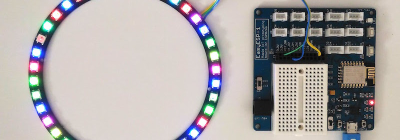
EasyESP-1 driving NeoPixel ring
Connection between the NeoPixel ring and ESP8266 is through a single data wire. I am using EasyESP-1 here for illustration. The Data In (DI) line of the NeoPixel ring connects to D1 pin of EasyESP-1. VCC and GND pins go to 3.3V and GND terminals of EasyESP-1. I used a 40 RGB LED NeoPixel-compatible LED ring from Elecrow for this experiment.
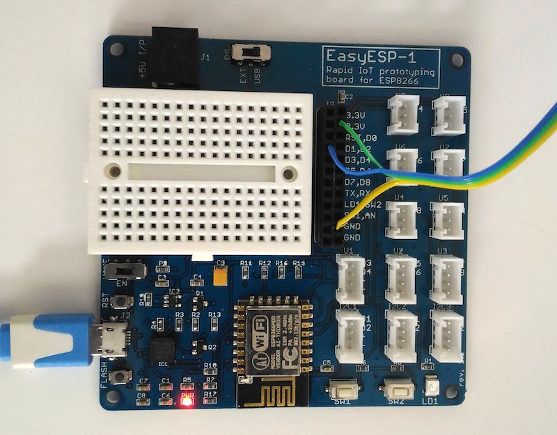
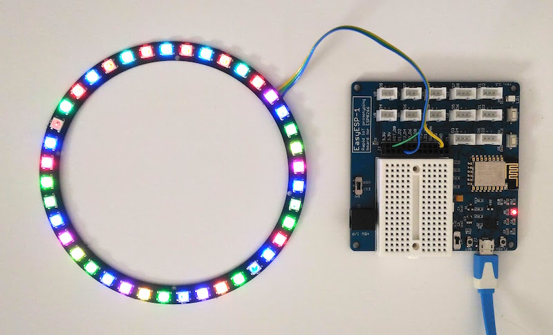
Wiring RGB LED ring to EasyESP-1
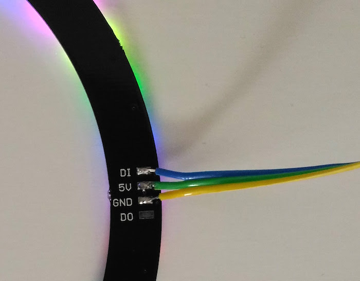
Power supply and data input pins on the back of Elecrow’s RGB LED ring
For programming the ESP8266 to drive the RGB ring, you will need to install Adafruit’s NeoPixel Library. The library comes with several examples which can be tested with the current setup with a very little modification in the code. Once the library is installed, open RGBWstrandtest example and modify the following two lines as follows:
#define PIN D1
#define NUM_LEDS 40
That’s all you need to change to run this example with the current setup of the EasyESP-1 and RGB LED ring.
Note that you must have your Arduino IDE setup to program ESP8266 according to the instructions posted in Tutorial 1: Setting up the Arduino IDE for EasyESP-1 prior to run this example.
Then upload the modified example code and see the output.
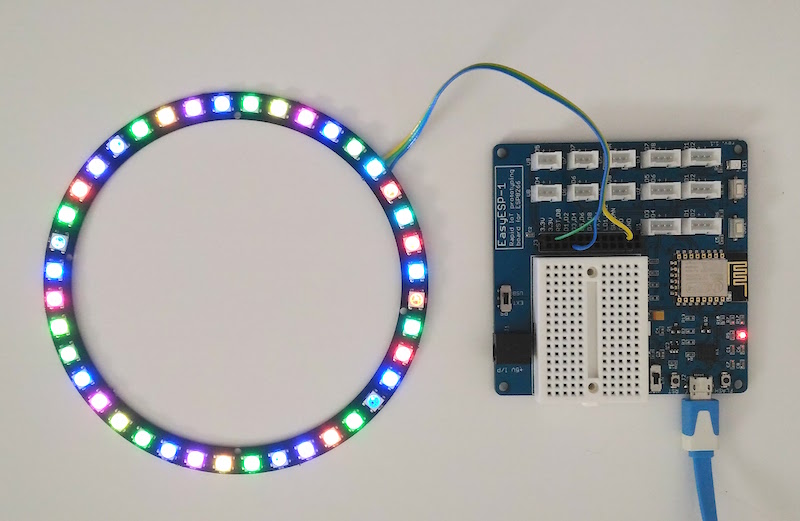
RGBWstrandtest output