Tag Archives: PIC Project


Programmable LED dimmer using PIC16F18325

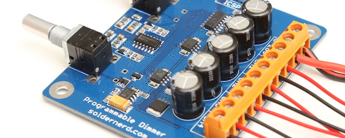
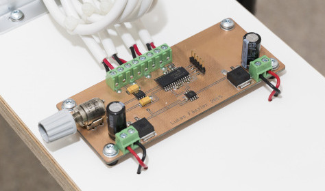
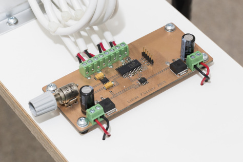
LUKAS FÄSSLER designed a versatile programmable LED dimmer using PIC16F18325 MCU to drive white and RGB LEDs. It operates at a wide range of power supply (6 to 26 volts) and utilizes MOSFET drivers with non-inverting outputs.

Programmable LED dimmer

Programmable LED dimmer

The mosfet drivers are basically the same as before but now with non-inverting outputs: LM5111-1M. There are two of them for a total of 4 outputs compared to only 3 with the previous version.
They now drive much (physically) smaller but no less capable mosfets which allowed me to significantly downsize the whole board to 75x65mm.  The NXP BUK9Y12-40E are rated at 40 volts and offer an on-resistance of 12 milliohms (max @ 25 degrees ) with a 5V drive as we have here. Their large thermal pads a the bottom (NXP calls that package LFPAK) pass heat efficiently to the PCB which then serves as a heat sink. There is also a 30V version that offers even better performance but with a maximum input voltage of 26 volts I thought the 40V version is the safer choice.

Another minimalist wrist watch, but with binary display

Earlier this week, we saw David Johnson-Davies’ minimalist ATtiny85 wrist watch that displays time using 12 LEDs arranged in a circle like a watch dial. I found another interesting LED-based wrist watch design shared by MACROFAB. It is a low cost watch based on Microchip PIC16F527 and it displays time in binary format. The PIC microcontroller runs in low-power crystal mode using a 32.768 KHz external crystal, that helps to achieve an accurate 1Hz signal required for timekeeping.

Wrist watch with binary display

Wrist watch with binary display

The Macro_Watch has 11 LEDs. Four LEDs for the Hour (H1 – H4), Six LEDs for the Minute (M1 – M6), and a single Seconds LED for timing purposes. This guide will not go into how to read binary but a good guide can be found here. Pressing the switch on the front will lit up the LEDs for 10 seconds to allow reading of the time. Holding the switch for 3 seconds will allow setting the current time. The time advances with acceleration so the longer the button is pressed the faster the time will increase. There is no AM/PM indicator on the watch. The SEC LED can be repurposed for AM/PM use or the user can look outside and see if the sun is out.

Programmable relay switch using PIC MCU (revised version)

Programmable relays are key elements in numerous automation applications such as automatic street light control, watering and pump control, HVAC, home automation, power plants automation in industries, etc. This article describes a DIY programmable relay switch using PIC16F1847 (PIC16F628A can also be used) microcontroller. It is a revised version of my previous PIC-based relay timer project with added features and some improvements in the circuit design part. Like my previous version, it also allows you to set both ON and OFF times. The maximum time interval that you can set for ON and OFF operations is 99 hours and 59 minutes. The new version features cyclic option, which means you can choose to run it in a continuous loop of ON and OFF cycles. The timer can be programmed through 4 push switches. The programming menu, relay status (ON or OFF), and number of cycles completed are displayed on a 16×2 character LCD. The timing resolution of this relay timer is 1 minute. The timer also saves the previously-set ON/OFF times and the cyclic option in its internal EEPROM so that it can retain these values after any power supply interrupt. The firmware for this project is provided for both PIC16F1847 and PIC16F628A microcontrollers.

PIC

Programmable relay timer switch

Here are the summary of the features that this programmable relay switch has:

  • On-board +5V voltage regulator (operates at 9-15V DC input)
  • OFF and ON time setup for the relay operation
  • Option for cyclic run (maximum 100 cycles, after which the timer stops automatically)
  • Stores ON/OFF times and Cyclic option from previous setup into internal EEPROM
  • ON/OFF timing range: 0 to 99 hours and 59 minutes with 1 min resolution
  • Interactive user interface using 4 tact switches and a character LCD
  • On-board buzzer alarm
Read more

LED light dimmer using PIC16F1936

Lukas Fassler recently moved to a new apartment and he wanted to have a PWM LED light dimmer to control some of his 12V LED strips. When he didn’t find a ready-made one that would meet his requirements, he designed his own using the PIC16F1936 MCU. His PWM dimmer can handle 100W output power at 12V DC.

PWM dimmer for LED strips

PWM dimmer for LED strips

At the center of my design is a 8-bit PIC microcontroller, a PIC16F1936. There’s not much special about this particular model, it’s just a type I’ve used several times before and still had some on stock.

A LM2931 provides the PIC with 5 volts from the 12 volts input voltage. I use the LM2931 as my standard 5V regulator. It’s pin compatible with the legendary 7805 but survives input voltages in the range of -50 to +60 volts making it very robust against transients.

« Older Entries