Tag Archives: pic16f628a


Lab 19: Play musical notes

We have discussed in the past experiments how to use a PIC microcontroller to do a variety of things from flashing an LED to driving a motor, etc. Today, we will see how to play notes of a song with a PIC microcontroller. Musical notes are simply sound waves of particular frequencies. If the frequency of a note is known correctly, a microcontroller can be programmed to play the note by generating a square wave (of the same frequency) signal at one of its I/O pins. The signal must be fed to a speaker to listen to the sound. Here, we will discuss playing notes of the popular “Happy birthday to you” tune using a PIC16F628A microcontroller and a buzzer.

Musical notes using a PIC micro

Read more

Lab 17: Sleep and Wake PIC microcontrollers

PIC microcontrollers’ Sleep feature is an extremely useful mechanism to minimize power consumption in battery-powered applications. In Sleep mode, the normal operation of a PIC microcontroller is suspended and the clock oscillator is switched off. The power consumption is lowest in this state. The device can be woken up by an external reset, a watch-dog timer reset, an interrupt on INT0 pin, or port-on-change interrupt. In this experiment, we will discuss how to put a PIC microcontroller into Sleep mode and compare the current consumption during Sleep mode and the normal operation mode.

Understanding Sleep mode

Read more

Lab 13: Read and Write to internal EEPROM

EEPROM (Electrically Erasable Programmable Read-Only Memory) is a type of non-volatile memory which can be programmed, erased, and re-programmed electrically while it is on the circuit board. A majority of PIC microcontrollers come with some built-in EEPROM which is a great place to store data that should not be lost when the system is powered down. A good example is a digital lock system where the access code can be stored in the EEPROM of microcontroller so that the contents remain intact even after the power supply has been removed. In my ‘Beginner’s data logger‘ project, I used the internal EEPROM of PIC12F683 to store the measured temperature values. In today’s experiment, we will learn how to perform the basic Read and Write operations to the internal EEPROM of PIC16F628A.

Read/Write operation with PIC's internal EEPROM

Read more

Lab 11: Multiplexing seven segment LED displays

In Lab 6, we discussed about interfacing a seven segment LED display to a PIC microcontroller. The seven segments were driven individually through separate I/O pins of the microcontroller. If we do just like that then for 4 seven segment LED displays, 28 I/O pins will be required, which is quite a bit of resources and is not affordable by mid-range PIC microcontrollers. That’s why a multiplexing technique is used for driving multiple seven segment displays. This tutorial shows how to multiplex 4 common anode type seven segment LED displays with a PIC16F628A microcontroller.

Multiplexing 4 common anode seven segment LED displays

Read more

2-Wire Keypad Interface Using a 555 Timer

Keypads are a very commonly used input device in microcontroller-based systems. In a keypad, multiple switches are arranged in rows and columns so that they could be interfaced to a microcontroller with a minimum number of I/O pins. For example, a 12-key keypad is arranged in a 4×3 format, which allows to interface the 12 keys to a microcontroller with only 7 connections. The location of each key on the keypad is defined by two coordinates: the row and the column. When a key is pressed, it connects its row with its column. The microcontroller must scan all the rows and columns to find out which key has been pressed. This is the most common way of interfacing a keypad to a microcontroller. There are tons of resources on the internet regarding this technique and so I am not going to discuss it here.

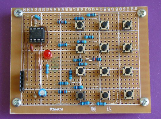
Today, I am going to share with you about a new keypad interfacing technique that uses only two I/O pins of a microcontroller: one for signalling the microcontroller when a key is pressed, and the other is to read the key information. It is based on a 555 timer IC which is configured as an astable multivibrator. I am not sure if anybody has ever tried using a 555 IC for keypad interfacing, but this technique really works. I am going to demonstrate this with a 4×3 keypad (a standard telephone dial pad). A PIC16F628A microcontroller will read the output of a 555 timer IC, determine what key has been pressed, and display it on a character LCD module.

Read more

« Older Entries Recent Entries »