Most of the microcontroller based data loggers use external EEPROM chips for storing the measurement values. This increases the cost, power consumptionm, and the size of the circuit board. Instead, why don’t we choose a microcontroller with a larger flash memory and use it for storing the data. Actually, a data logger’s firmware is not very big in size. So, the remaining flash memory can be used to store the data from realtime measurements. This project is based on the same concept and uses a PIC18F27J53 microcontroller that has 128K programmable flash memory. The PIC18F27J53 family microcontrollers are low power and high performance 8-bit MCUs with Integrated full-Speed USB 2.0. They have Deep sleep mode feature for low power application, and a RTCC module for real time applications.The analog to digital converter (ADC) module is 12-bit, so it gives better resolution.

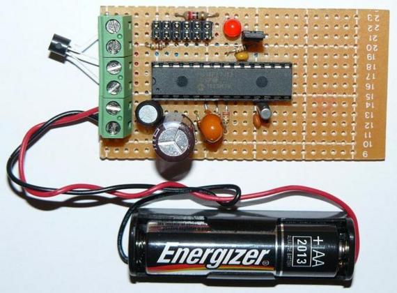
The beauty of this project is it runs with a single AA cell battery. Wait a minute, how that could be possible. The operating voltage for PIC18F27J53 is between 2-3.6 V, and an AA cell battery can only provide 1.5 V. Yes, it has a voltage booster circuit to up-convert the 1.5 V from the battery to the required voltage level. And the switching for the boost circuit is provided by the microcontroller’s PWM output itself. So, how does the microcontroller start at the beginning? Yes, it requires a jump start at the beginning. That can be done by simply supplying the power from a USB cable at the beginning, then the microcontroller will pick up the power from the battery itself. This is a very interesting project.
Read more