Introduction
Seven segment LED displays are often found in clock radios, VCRs, microwave ovens, toys and many other household items. They are primarily used to display decimal numbers but they can also display a few alphabets and other characters. This experiment describes interfacing a seven segment LED display to a PIC16F688 microcontroller. You will make a hexadecimal counter that counts from 0 (00h) to 15 (0Fh) and display the value on the seven segment LED display.
Required Theory
A seven segment LED display is an special arrangement of 7 LED elements to form a rectangular shape using two vertical segments on each side with one horizontal segment on the top, middle, and bottom. By individually turning the segments on or off, numbers from 0 to 9 and some letters can be displayed. Seven segment displays sometime also have an eighth segment to display the decimal point. Therefore, a seven-segment display will require seven outputs from the microcontroller to display a number, and one more output if the decimal point is to be displayed too.
The segments are marked with non-capital letters: a, b, c, d, e, f, g and dp, where dp is the decimal point. The 8 LEDs inside the display can be arranged with a common cathode or common anode configuration. With a common cathode display, the cathodes of all the segment LEDs are tied together and this common point must be connected to the ground. A required LED segment is then turned on by applying a logic 1 to its anode. In common anode displays, all the anodes are tied together and the common anode is connected to the supply voltage Vcc. Individual segments are turned on by applying logic 0 to their cathodes.
When more than one seven segment display is used, a multiplexing technique is used to minimize the required number of microcontroller pins. We will discuss about that technique later.
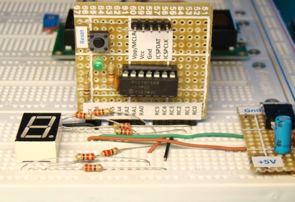
In this experiment, a LT543 model common cathode seven segment display is used. The segment LEDs glow red when turned on. The module has 10 pins whose configuration is shown below.

Read more