Wifi enabled 8×64 pixel LED matrix display
|
|
This project is a modification of my previous Bluetooth-enabled LED matrix display project, which used 8×64 monochromatic LED matrix (total 512 LEDs) for displaying scrolling text message. The original project used Bluetooth for display data transfer from a smartphone, but this one now uses Wifi. The display message is sent through web browser to a ESP8266 module that is configured as a web-server. No Arduino or any other microcontroller is used. ESP8266 alone works as a WiFi server and drives the MAX7219-based LED matrices.
Wifi-enabled scrolling led matrix display
Hardware Setup
Things needed (available on my Tindie Store):
- Easy Matrix modules (8 pcs)
- Dual power supply module (1 pc)
- NodeMCU ESP8266 board (1 pc)
- Wires, enclosures, etc
The 8×64 pixel display matrix is constructed using eight Easy Matrix display modules in a cascade.
What is Easy Matrix?
Easy Matrix is an easily cascadable 8×8 monochromatic LED dot matrix display module with onboard MAXIM’s MAX7219 LED driver chip. The MAX7219 allows you to drive the LED matrix using only three I/O pins of Arduino or any other microcontroller. The LED matrix module used in Easy Matrix has a bigger dot size (5mm) and has the overall display dimensions of 60.2mm x 60.2mm (2.4″x2.4″). It is easily cascadable in series with the help of precisely aligned male and female header pairs located on the left and right sides of the display module. With lots of freely available Arduino libraries for MAX7219 chip, this module is easy to use in any Arduino project for displaying basic text and animation.
You can buy Easy Matrix Kit from our Tindie Store.
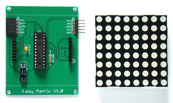
Easy Matrix module
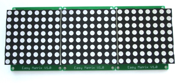
3 Easy Matrix boards cascaded together
Wiring
For this project, I used 8 Easy Matrix modules cascaded in series to construct a 8×64 LED matrix display. The input header of Easy Matrix are located on right side and consists of three signal lines (DIN, CLK and LOAD) and two power supply lines. The signal lines are driven using the ESP8266 SPI pins. So, connect DIN, CLK and LOAD pins of the rightmost Easy Matrix input to D7 (GPIO13), D5 (GPIO14), and D3 (GPIO0) pins of NodeMCU, respectively. The 5V DC supply for Easy Matrix and 3.3V for NodeMCU are provided using a Dual (+5V/3.3V) regulated power source. These components are all enclosed into a customized box made out of furring strip boards from Home Depot. Note that while programming the NodeMCU board, no external power supply is required as it is supplied from the USB port. But when it is placed inside the enclosure with other display modules, its 3.3V pin should be connected to the 3.3V pin of the dual power supply board. Following figure shows the connections between the power supply, NodeMCU, and LED matrix panel.
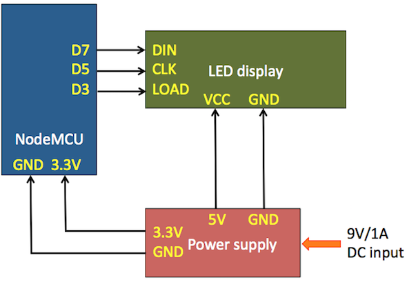
Wiring between the different modules
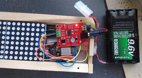
8 Easy Matrix boards, NodeMCU and power supply board inside the enclosure
The input to the power supply module can be provided from a 9V/1A rated DC wall adapter. For portable use of the display, I use a 9.6V Ni-MH battery pack for input power.
Software
For this project, the NodeMCU is programmed using Arduino IDE. You will need to setup ESP8266 Arduino core for this. Other Arduino libraries required are Max72xxpanel, and Adafruit_GFX. The project also requires ESP8266 Wifi support libraries that get preinstalled with the ESP8266 Arduino core setup. The NodeMCU is programmed to act as a webserver in the local Wifi network. The IP address of the webserver is displayed on the LED matrix scrolling from right to left when the project is powered on. Then type in the same IP address in the URL field of a web-browser on a computer that is connected to the same network. The ESP8266 webserver returns a data entry field to the browser screen, where you can enter the text message that you would like to be displayed on the LED matrix.
Download code: Easy_Matrix_demo1_scrolling_message_wifi_2
Note: Make sure you change the SSID and password in the code to match with your network.
Output
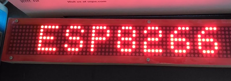
After uploading the code to ESP8266, when the display is powered on, you will see the IP address of the ESP8266 Webserver scrolling on the LED matrix panel.
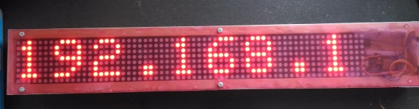
IP address of the webserver
Next, type in this IP address on your computer browser, you will see the following page is returned by the ESP8266. The computer must be on the same WiFi network.
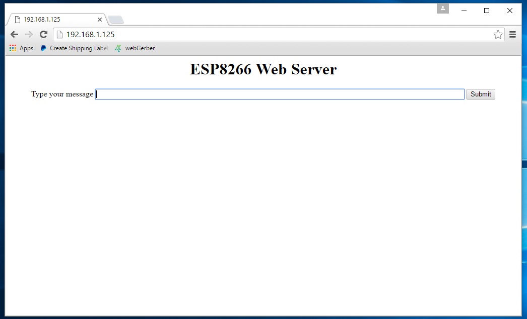
ESP8266 webserver page
Type in the message that you would like to send to the display and hit Submit button. The message is received by the ESP8266 webserver and is displayed on the matrix panel.
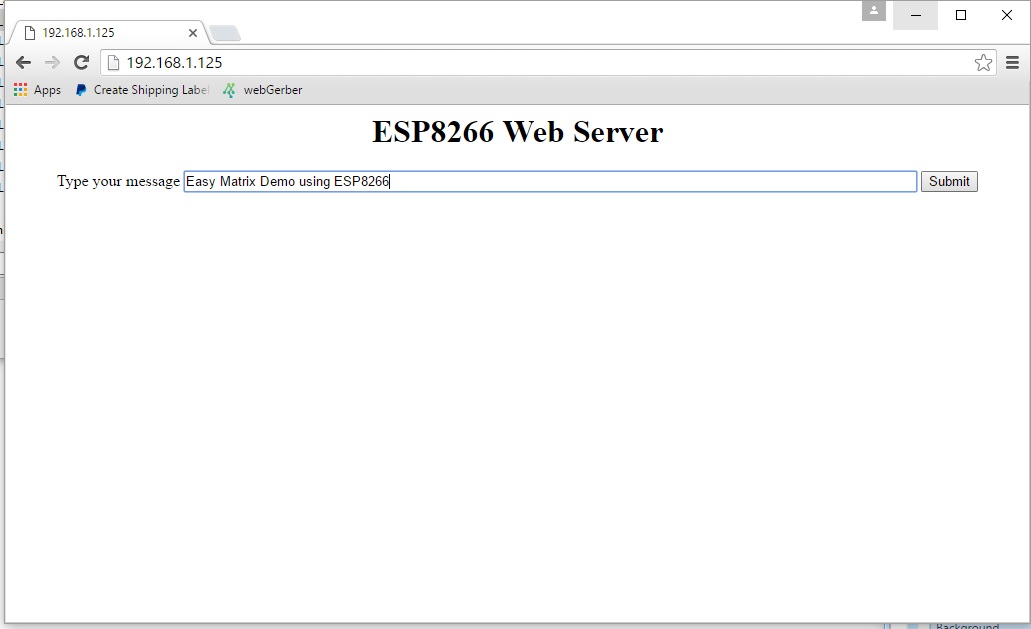
Type in the message in the message field
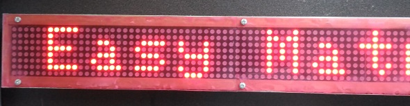
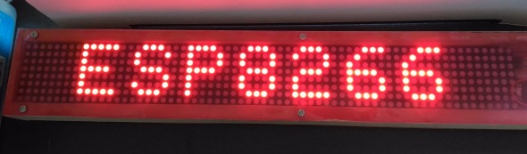
Message sent from the web interface is displayed on the LED matrix scrolling from right to left
I hope you enjoyed reading this project. You can use the above links if you are interested to buy the major parts required to build this project.
|
|
Hello,
Program works fine. I have some problems with the international characters (I live in France) I have to display “é è à ç ù ë ê â ä û ü î ï .etc” this is not working. I tried character replacement extending your list but no success. Is this limited by the Max circuit ?
Do you have a correspondance list from the font.h file attached to the project ?
Excellent project Sir, it scrolls text right away, Can a buzzer be installed or a gpio could be set high for a second upon ” new messages arrival” …
Thank you so much
i am fresher and i want to perform this project.can anyone give me the detail information about this project like in which software we can run the code and how to install nodemcu on wifi module.please tell me its urgent….
Very nice, I will try it 🙂
no respone seen what might be the proBLEM
hi I try this one using 4in1 8×8 led matrix problem is the character is different, pls see image attached. anyone can help which one should i change..
https://imgur.com/w8AGcHr
There are many types of hard ware wirings
.you may try MD_max72xx lib which has hardware configuration in heder file.
Try changing this:
matrix.setPosition(0, 1, 0);
matrix.setPosition(1, 1, 0);
matrix.setPosition(2, 1, 0);
matrix.setPosition(3, 1, 0);
etc.
To this:
matrix.setRotation(0, 1);
matrix.setRotation(1, 1);
matrix.setRotation(2, 1);
matrix.setRotation(3, 1);
etc.
Worked for me.
Hi, got the project to work. Thanks for the article. I was wondering if you could post a mod for this that shows how to save the submitted message into EEPROM so that if power is cut, and later restored, that the message will be read from EEPROM storage and displayed until changed? This would be quite useful!
Hi! I made this project and it’s working perfectly. Is there any way that I can control the setup remotely from the internet anywhere and not just from my local network? Could you please offer some suggestions as to how I might be able to accomplish this.
Thank you!
Take a look at WiFi Manager: https://github.com/tzapu/WiFiManager
hello sir, i am trying to do to the same project..
i am unable to write the program,can u help me and send the program codes
Nice tutorial, works great with 16 LED matrixes
I’m trying to make it work with 32 LED matrixes but there seems to be a limit of 16 LED matrixes, above 16 displays it does not work, any idea what could be the limiting factor?
Hans,
When you said it works with 16 LED matrices, did you mean 16 8×8 modules? I haven’t tested it beyond 10 8×8 modules. So you might need to look into the libraries used if there are any limitations there.
Yes, I mean 16 x (8×8) modules.
I tried anything I could imagine but couldn’t find anything that solves the problem.
I had one made with 24 x (8 x 8) matrix modules. Are matrix of 32 x 32 mm, using Smooth_Scrolling through EPS8266, same system. Works perfectly.
Hi, if i understand right the module should connect to the wifi router. is there a way to start a wifi server on the same module? i want to connect only to the module to print msgs.
Very good without work congratulations, I’m using it with the matrix Easy Matrix V1.0 from your store.
How do I not delete (lose) the message when I disconnect the Node Mcu card? (no light)
Light fall
How do I set fixed IP in code?
thank you
Sorry my english.
I need to control:
matrix.setIntensity(10); and speed direct in the browser. like this:
“Type your message ”
“Value of speed ”
“Luminous ”
What else do I have to change in the code ?
thanks
How do I remove the delay when the loop ends? also can we change the speed?
Thanks
To change the speedy, must change the value of delay.
int wait = 250; // In milliseconds
How to rotate the Letter.
I already get it by
matrix.setRotation(0,1)
hi I try it but only one character is rotated 🙂
Hello,
Add lines below matrix position : for example :
matrix.setRotation(0, 1); // Rotation 1rst char
matrix.setRotation(1, 1); // Rotation 2d char
matrix.setRotation(2, 1); // Rotation 3rd char
matrix.setRotation(3, 1); // Rotation 4th char … etc