PIC-based Digital Voltmeter (DVM)
|
|
Introduction
This project will describe how to make a simple digital voltmeter (DVM) using a PIC16F688 microcontroller. The range of this DVM is 0-20V, but you can easily increase or decrease the range of input voltage as your requirements after you understand the voltage scaling method described in this project. The PIC micro reads the input voltage through one of the 8 analog channels and convert it to a 10-bit digital number using the internal ADC. Doing some math with ADC conversion (you will see later), this number can be converted to the actual measured voltage. The voltage is displayed in an HD44780-based character LCD.
Circuit Diagram and Description
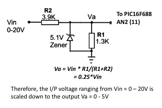
You cannot feed a 20V signal directly to a PIC microcontroller’s input channel. It is too higher than its operating voltage, and the microcontroller could be damaged. So, first we need a voltage scaler that will scale down the input voltage to the safe operating voltage range of PIC16F688. It can be achieved by a simple resistor divider network shown below.
 Using two resistors, R1 and R2, the input voltage ranging from 0-20V can be down converted to 0-5V. For the chosen values of R1 and R2, you can see that the output (Va) from the resistor divider network is 1/4th of the input voltage. If the input voltage goes beyond 20V, Va will exceed 5V, and this could be harmful for the PIC microcontroller. If you connect a 5.1V Zener diode across the R1 resistor, the output voltage Va will never exceed 5.1V. This will protect the microcontroller from any possible damage due to high voltage input. The voltage Va will go to AN2 (pin 11) channel of the PIC16F688 microcontroller. The rest of the circuit is shown below.

The LCD display is connected in 4-bit mode. If you have just 14 pins in your LCD module, then you may not have a back-light facility and you can ignore the pins 15 and 16. The contrast adjustment is done through a 5K potentiometer connected between +5V and Gnd. An in-circuit serial programming (ICSP) header is provided so that you can easily upgrade the firmware inside the PIC microcontroller in future if you make any changes. An external reset is helpful to bring the entire system to a known initial condition, when the microcontroller stops executing the program for some reason.
The complete circuit built on a breadboard is shown here. You need a regulated +5V power supply for this project (Why regulated? You will find the answer in the Software section below). You can use a LM7805 linear regulator IC for this purpose (read my article Regulated Power Supply for your Breadboard).

Software
Before writing the code for this project, you need to do some math related to AD conversion. You know that any application that uses analog-to-digital converters (ADCs), requires a fixed reference voltage to provide accurate digital count for input analog signal. If the reference voltage is not stable, the ADC output is meaningless. In this project, the reference voltage for ADC operation is selected to be Vdd (= +5 V). This is done by clearing the VCFG bit in ADCON0 register. Therefore, the ADC will convert any input voltage between 0-5 V in to a digital count between 0-1023. A major source of error in this project is the accuracy of R1 and R2 resistors. You are recommended not to use the rated values of the resistors. Rather measure their values with a good quality digital multimeter, and use those values for your calculation. What I found is R1 = 1267 ? and R2 = 3890 ?. Now,
0 – 5 V Analog I/P is mapped to one of the 1024 levels (0-1023 Digital Count)
=> Resolution = 5/1024 = 0.0049 V/Count
To avoid floating point, use I/P voltage = 2*Digital Count. Here’s how it works. Suppose, Vin = 4.6V. Then,
In the 4-digit product (0462), the first two digits are the tens and units digits of measured voltage. and the last two are the decimal digits. So, the measured voltage will be 04.62 V. Only the first three digits will be displayed (04.6 V).
Oscillator -> Internal RC No Clock
Watchdog Timer -> Off
Power Up Timer -> On
Master Clear Enable -> Enabled
Code Protect -> Off
Data EE Read Protect -> Off
Brown Out Detect -> BOD Enabled, SBOREN Disabled
Internal External Switch Over Mode -> Enabled
Monitor Clock Fail-Safe -> Enabled
/* Project: Digital Voltmeter based on PIC16F688 Internal Oscillator @ 4MHz, MCLR Enabled, PWRT Enabled, WDT OFF Copyright @ Rajendra Bhatt Oct 10, 2010 */// LCD module connections
sbit LCD_RS at RC4_bit;
sbit LCD_EN at RC5_bit;
sbit LCD_D4 at RC0_bit;
sbit LCD_D5 at RC1_bit;
sbit LCD_D6 at RC2_bit;
sbit LCD_D7 at RC3_bit;
sbit LCD_RS_Direction at TRISC4_bit;
sbit LCD_EN_Direction at TRISC5_bit;
sbit LCD_D4_Direction at TRISC0_bit;
sbit LCD_D5_Direction at TRISC1_bit;
sbit LCD_D6_Direction at TRISC2_bit;
sbit LCD_D7_Direction at TRISC3_bit;
// End LCD module connections
char Message1[] = “DVM Project”;
unsigned int ADC_Value, DisplayVolt;
char *volt = "00.0";
void main() {
ANSEL = 0b00000100; // RA2/AN2 is analog input
ADCON0 = 0b00001000; // Analog channel select @ AN2
ADCON1 = 0x00; // Reference voltage is Vdd
CMCON0 = 0x07 ; // Disable comparators
TRISC = 0b00000000; // PORTC All Outputs
TRISA = 0b00001100; // PORTA All Outputs, Except RA3 and RA2
Lcd_Init(); // Initialize LCD
Lcd_Cmd(_LCD_CLEAR); // CLEAR display
Lcd_Cmd(_LCD_CURSOR_OFF); // Cursor off
Lcd_Out(1,1,Message1);
Lcd_Chr(2,10,'V');
do {
ADC_Value = ADC_Read(2);
DisplayVolt = ADC_Value * 2;
volt[0] = DisplayVolt/1000 + 48;
volt[1] = (DisplayVolt/100)%10 + 48;
volt[3] = (DisplayVolt/10)%10 + 48;
Lcd_Out(2,5,volt);
delay_ms(500); // Hold for 500 ms
} while(1);
} // End main()
Testing the DVM
Here are the DVM measurement output for various input voltages ranging from 0-20V obtained through a variable DC power source.

Variable power supply source


Questions, comments, and suggestions are welcome.
|
|
Please R-B your site has been very helpful to me. But there is something I want to understand very well in DVM program code. that %10 what does mean? why is it there?
hi. i was wondering if you could provide me the code for making your LCD voltmeter into an LED type voltmeter.
thank you.
ron
I have voltage divider circuit as this in many projects. However, I always omit zener as it is almost impossible to get precise voltage with. Every zener require minimum current in order to work properly, otherwise, voltage drop is significant. With 3.9K and 1.3K it allow 3.85mA, which may be good enough for 5mA rated zener, however that is only a fraction of mA current which is usually required for commonly available zener diodes, which usually requre even 40mA in order to work properly. And that kind of current may destroy PIC (max. limit for I/O pins is 5.5V, 20mA by datasheet).
This further require more expensive and less common 1-2W lower resistor values, or making it with more usually several resistors in series/parallel or both, in order to satisfy minimum required current of 40mA. However, that is not very good practice, as dissipation is enormous (1W or more) and as well require additional resistor to limit 40mA under 20mA.
Thus this become unresolved chicken and the egg problem without few mA rated zener. I’m unsure how to solve this instead to omit zener completely and ensure voltage is always under maximum designed limit. Hopefully, all these are hobby projects, for my own pleasure.
i want to control the 5 Leds with potentionmeter..
like as,, ups charging level
hy sir,,
i want to control the 5 Leds with the potentiometer….
like as,, ups charging level
plz,,
my mail,,,adamubaid1@gmail.com
hello friend RB
i am measure (0-250V) i change the code
char *volt1 = “000.0″;
volt1[0] = DisplayVolt1/10000 + 48;
volt1[1] = (DisplayVolt1/1000)%10 + 48;
volt1[2] = (DisplayVolt1/100)%10 + 48;
volt1[4] = (DisplayVolt1/10)%10 + 48;
Pls correct me if I’m wrong.
Hi friend ,
nice work frd,
how to change the code & circuit to measure the voltage AC (0-600V) please help friends
thank you sir
I need program in c using pic microcontroller. It must compile in microc compiler and the program title ” Resistance measurement”. it must display in LCD Displayand the formula R4=(R3xVo)/ (vcc-vo).
nice post it will help me lots can you give me idea that how can i make digital ammeter ( current meter) using pic16f877a
Hi, very nicely done. I wanna know that how can one make an embedded system to measure 120 volt dc ? I am looking for some ADC but can not find it. Can you please help me in finding a solution? Thanks.
Hi Raj!
Very good project, but how did you find the resistor value?? try and error?
thank you!
marC:)
I think in this circuit you are measuring voltage drop across 1.3kOhm resistor is that right?
Hey! I was wondering where in this voltage divider circuit could I connect my load… say I have a 8W bulb that requires 12-18VDC.
Sorry, I am not an electrical engineer. Any help would be appreciated.
will this work if i try to measure a negative voltage drop?
And if not, what modifications should i do to this project so that it can also measure negative voltage drop?
hello ..
1.Can i measure 220v ac supply without converting ac to dc?
2.The ground of vin 550 ac voltage are the same connected to the ground of zener diode protect the PIC?
I have an application. I want to measure a DC voltage across a capacitor, should be 9 volts to start with hen a 9 volt battery is initially attached. After 5 seconds or so, it should drop to near zero. It is a crude way to see if the capacitor is good. I apply voltage, measure it to see if it is fully charged and get 9 volts dc. If I leave the measuring wires on it and take another measurement 5 seconds later, it should be near zero. I don’t want to display the voltage, just see if that process happens. If it does, I want a green LED to light. If it doesn’t, a red led will light. Its for a device buried under ground and we do not want to use a meter by the technician. If the capacitor was shorted, the starting and ending voltage would be the same. If it was open, we would get zero voltage both times.
Initially, we were going to just use an LED and resistor for a measuring device. Depending on the capacitor value, the LED would light brightly and then gradually dim. This would indicate a good capacitor. The problem was we thought it might be too complicated for a field tech. We thought a red/green bad/good LED would be better. What do you think. Would this chip be good for that? I’m a new pic chip guy and have not written any code yet. I do have a programmer and breadboard.
hello
first of all I want to congratulated you about your projects
really it’s fantastic , I’m learning many thing from it.
now I’m trying to do this project but on pic 18f4620 I try to write a code bus i’m facing some problem.
could you please help me in that??and what about the circuit for project it’s still same , isn’t it ??
Please answer me as soon as u can.
thank you
best wishes 🙂
hello,
really love this project and wish to try it at home. but you did not give a step by step approach on how to get the bread board wired up with the components.As am a new electronic student i will be glad if you could get in touch with the steps. I will also love to buy the componets complet and try to assemble it with your guidance.
Thank you
reply really appreciated!!!
Hi RB,
I need your help on based on this project using PIC16F688,i’m working on one project which is need 3 of analog channel,i have did the hardware part and selected AN2,AN4 and AN5 which are the three channel,i had refer this project and your anther power supply project which is 2 channel,below is my coding,but it working only AN2 channel.
I’m new for pic programming.Please help see through the codes and give me some advise.Look for your sooner reply,thanks
Greetings from Shi Ping
sbit LCD_RS at RC4_bit;
sbit LCD_EN at RC5_bit;
sbit LCD_D4 at RC0_bit;
sbit LCD_D5 at RC1_bit;
sbit LCD_D6 at RC2_bit;
sbit LCD_D7 at RC3_bit;
sbit LCD_RS_Direction at TRISC4_bit;
sbit LCD_EN_Direction at TRISC5_bit;
sbit LCD_D4_Direction at TRISC0_bit;
sbit LCD_D5_Direction at TRISC1_bit;
sbit LCD_D6_Direction at TRISC2_bit;
sbit LCD_D7_Direction at TRISC3_bit;
// End LCD module connections
// Define Messages
char message1[]= “USCC”;
char message2[]= “V=”;
char message3[]= “I=”;
char message4[]= “Temp=”;
// End Message
unsigned int ADC_Value, DisplayVolt,DisplayCurr, DispayTemp;
char *volt= “00.0”;
char *amp=”0.000″;
char *temp=”000.0″;
void main() {
ANSEL= 0b00000100; // RA2,RA4,RA5 are analog input
ADCON1 = 0x00; // Reference voltage is Vdd
CMCON0=0x07; //Disable comparators
TRISC = 0b00000000; // PORTC All Outputs
TRISA = 0b00111100; // PORTA All Outputs, Except RA5,RA4,RA3 and RA2
Lcd_Init(); // Initialize LCD
Lcd_Cmd(_LCD_CLEAR); // CLEAR display
Lcd_Cmd(_LCD_CURSOR_OFF); // Cursor off
Lcd_Out(1,1,message1);
do{
//Read volt
Lcd_Out(2,1,Message2);
ADCON0 = 0b00001000;
ADC_Value = ADC_Read(2);
DisplayVolt = ADC_Value;
volt[0] = DisplayVolt/1000 + 48;
volt[1] = (DisplayVolt/100)%10 + 48;
volt[3] = (DisplayVolt/10)%10 + 48;
Lcd_Out(2,3,volt);
Lcd_Chr(2,8,’V’);
//Read amp
Lcd_Out(2,1,Message3);
ADCON0 = 0b00010000;
ADC_Value=ADC_Read(4);
DisplayCurr=ADC_Value /22527;
amp[0] = DisplayCurr/10000 + 48;
amp[2] = (DisplayCurr/1000)%10 + 48;
amp[3] = (DisplayCurr/100)%10 + 48;
amp[4] = (DisplayCurr/10)%10 + 48;
Lcd_Out(2,3,amp);
Lcd_Chr(2,9,’A’);
//Read temp
Lcd_Out(2,1,Message4);
ADCON0=0b00010100;
ADC_Value=ADC_Read(5);
DispayTemp=ADC_Value * 2;
temp[0] = DispayTemp/10000 + 48;
temp[1] = (DispayTemp/1000)%10 + 48;
temp[2] = (DispayTemp/100)%10 + 48;
temp[4] = (DispayTemp/10)%10 + 48;
Lcd_Out(2,6,temp);
Lcd_Chr(2,13,’C’);
}while(1);
}
Raj! The problem is showing again, it seems that the pin 11 of the pic doesnt work, i have changed the pic again, and it is always showing 20.4v which is frustrating because i made it for my mom’s birthday on septembre 9th
thank you for your help!
marC:)
Dear sir , I have need a LCD type MPPT SOLAR charge controller circuit diagram and hex code , c language, pls help
And how to purchase it from u
Hi RB,
thanks just stumbled on to your excellent site (you are doing good work, thanks for your time) I need to build PIC-based Digital Voltmeter, can you make it read 3 or 4 decimals after the . ex 12.2364 v, I do slow charging of big batteries and will be nice to see them coming up slowly. What do I need to change if it is possible? I have no programming knowledge and only build projects by using hex file supplied if it is possible, if it is possible.
Virus
I want to make the PIC microcontroller to measure a resistance ranging (0-2000 ohm).What change in the value of R1 and R2 and in the C-code i have to make for the input voltage of 5v
Perhaps it is some bug in programming, because I changed one of the sampling pins from AN0 to AN3 and again to AN0, and now it works perfectly!
But I have to mention that it works independently of what the ADCON0 register is set. In fact, even if I remove it from the code, it stil works!
I have a couple of questions to ask:
1) What does the ADCON1 do? The reference voltage is set by the 2nd bit of the ADCON0 register if you see the manual.
2) Why are the 2 LSB of the ADCON0 set “0”? If you see the manual, on page 71, the first LSB is actually the enable bit of the ADC module and it has to be “1”!
-> But as I mentioned before, there is some kind of bug, because even if I completely omit to set the ADCON0, it still works!
Now I’m going to implement a current meter as another of your projects. Hope I will succeed in this! Keep up the good work!
Greetings from Greece. 🙂
Hello. I have made many of your projects, and I highly encourage you to make more!
I tried to make a dual input voltmeter using pins AN0 and AN2, based on this project.
It reads from both pins, but if I connect only one of them, it displays on LCD both readings the same value! What is wrong? Please help me!
Here is the code:
sbit LCD_RS at RC4_bit;
sbit LCD_EN at RC5_bit;
sbit LCD_D4 at RC0_bit;
sbit LCD_D5 at RC1_bit;
sbit LCD_D6 at RC2_bit;
sbit LCD_D7 at RC3_bit;
sbit LCD_RS_Direction at TRISC4_bit;
sbit LCD_EN_Direction at TRISC5_bit;
sbit LCD_D4_Direction at TRISC0_bit;
sbit LCD_D5_Direction at TRISC1_bit;
sbit LCD_D6_Direction at TRISC2_bit;
sbit LCD_D7_Direction at TRISC3_bit;
unsigned int adc_v, DispVolt, adc_v2, DispVolt2;
char *volt = “00.00”;
char *volt2 = “00.0”;
void main() {
ANSEL = 0x00000101; // RA0, RA2 is analog input
ADCON1 = 0x00;
CMCON0 = 0x07 ;
TRISC = 0b00000000; // PORTC All Out
TRISA = 0b00010101;
Lcd_Init();
Lcd_Cmd(_LCD_CLEAR);
Lcd_Cmd(_LCD_CURSOR_OFF);
do {
ADCON0 = 0b00001000; // Analog channel select AN2
adc_v = ADC_Read(2);
DispVolt = adc_v * 1.174;
volt[0] = DispVolt/1000 + 48;
volt[1] = (DispVolt/100)%10 + 48;
volt[3] = (DispVolt/10)%10 + 48;
volt[4] = DispVolt%10 + 48;
Lcd_Out(2,12,volt);
delay_ms(100);
ADCON0 = 0b00000000; // Analog channel select AN0
adc_v2 = ADC_Read(0);
DispVolt2 = adc_v2 * 1.2;
volt2[0] = DispVolt2/1000 + 48;
volt2[1] = (DispVolt2/100)%10 + 48;
volt2[3] = (DispVolt2/10)%10 + 48;
Lcd_Out(2,1,volt2);
delay_ms(300);
} while(1);
}
Make sure there’s no short circuit between the two ADC inputs. What is your circuit diagram look like?
Hi george iam impressed by your ideas can you please send the circuit diagram of this project.
Thanks In Advance
Regards,
BASILEA RUBAN
thanks Raj! 🙂
my heart rate by fingertip doesnt work at all.. it gives 0 🙁
The problem is solved, that was my jumper shorted off!!!
thank you for all your beautiful project!
i encourage you to do more projects! 🙂
thanks a bunch!!!!
i really really appreciate what you are doing! 🙂
have a great day!
marC:)
I am glad you finally resolved this.
gnd pin
can you put it on a breadboard clearly for the resistor divider networks, so i will sleep tonight.. ;s
thanks a bunch!!!
Sorry Marc, I won’t be able to do that today as I am going to bed now. I have a flight tomorrow for Munich, Germany. I will be there for a week for a conference, and I will surely do it after I return back. There’s no -5V in my circuit.
Yes, my mistake, i have put 3.9k ohm resistor,anyway, what is wrong with my circuit pleaseee??
thanks!
marC:)
here’s the picture of my circuit : http://img577.imageshack.us/img577/3258/ressitordividernetwork.jpg
and it doesn’t work 🙁
pleaseeee help me!
i have been working about 3 hours now on this… i am tired.. now 🙁
thank you!
marC:)
There’s no 3.9 Ohm resistor in my circuit. It is 3.9K ohm.
Raj? Can you tell me what are these two resistors on the picture, you have mention putting R1 and R2, and now there’s 3 resistor?? i don’t quite understand…
http://img193.imageshack.us/img193/2017/voltmeterraj.jpg
thanks!
marC:)
i hope you will help me as soon as possible.
i’m counting on you!
best wishes!
Marc,
Those resistors are not the part of the circuit, so ignore them.
there is no short circuit, answer me in 1 year or two…
Marc,
If you are measuring a constant 20.4V it means your analog input voltage is always 5.0V because that will give 1023*2 = 2046, which is shown as 20.4V on LCD. Make sure there is no short circuit between AN2 and VCC pin.
no one can help me please?
i did everything shown on the schematic
thanks!
marC:)
The voltage from the battery to test is always 20.4v, anyway if i plug the battery to test or not, it’s the same result… i don’t understand.. now
what if i want to measure 220V Ac voltage ??
Thanks Raj! I will try it, i will let you know how it’s going…
thank you again!
marC:)
thanks for sharing the project! where do i connect the + and the – of the battery to be tested? thanks!
marC:)
+ of battery should go to Vin and – should go to ground of the circuit.
i am not using the icsp header and my circuit is not working
thanks
Yes Raj, i tried it the same, it gives me 5V + voltage of the source…
must be something i did wrong
thanks!
marC:)
dear sir yout 16f688 volt meter works ok!!!
but the 12f683 volt meter does not work can you help me
thanka.
using this project,i want to interface the pic 16f688 with pc and want to make a pc to pc communication network so that the device can be monitored from any place.please can u send me the hex code,program and circuit diagram
Input voltage is 0 to 20 volts and anything over the zener voltage goes to ground.
Why do you take this cheap wasteful way out ? Why not suggest a purpose made chip with low currebt to ground on overvoltage . Tey cost next to nothing and are common.
Hi Raj! I tried your project twice but for 0 v input it gives me 5 v and for 3 v input it gave me 15 v… i think did something wrong.. can you help me out please?
thanks!
marC:)
Marc,
Did you try this project exactly as it has been described, or are you using a different microcontroller?
how can i diplay the value in lcd in my pc. basically how to interface the input of pic16f688 with pc. please can you send me the hex code, program and circuit configuration.
And when i measure 50.00 wolts – what will be the resolution of the measurement
Hey thanks for this great work
I’m asking you if you can give me the code written in assembly code because I’m using THrsim11.
🙂 i forgot – R1 = 4k + 2k trim
Hello – I need from your help.
I want to measure Vin from : 00.00 V ~ 50.00 V
and selected for :
R1 = 5k ( + 2k multiturn trim for calibration ) , R2 = 50k To get into to have in the outlet of the divisor Va = 5 V , when Vin = 50 V
first :
Va = 5.555k * Vin/(5.555k+50k) = 0.0999*Vin => Va = 5
=> I/P voltage = 10*Va = 10* Digital Count * 0.0049
= 0.049 * Digital Count
= 0.05*Digital Count (Approx.)
Vin = 34.56V Then,
Va = 0.1*Vin = 3.456V
=> Digital Count = 3.456/0.0049 = 705.3061224
=> Calculated I/P Voltage = 490*705.3061224 = 345600
First 4 digits of 6 digit product
pls correct me if I’m wrong.
and when i have this numbers – where in the software need to i write .
+ this
volt[0] = DisplayVolt/1000 + 48;
volt[1] = (DisplayVolt/100)%10 + 48;
volt[3] = (DisplayVolt/10)%10 + 48;
volt[4] = DisplayVolt%10 + 48;
please give me all the software text ready for measurement of 00.00 to 50.00 V = I do not know where to record these numbers that I got
Voltmeter to both shows you two tensions – how to modify the scheme and the software text ?
I change the code for 2 inputs, but I don’t no if this is wright.
Please can you controle code of right place.
Friendly regards John.
/*
Digital Voltmeter 0-20V based on PIC16F688, 2 Analog Inputs
Internal Oscilator @ 4MHz, MCLR Enabled,PWRT Enabled, WDT OFF
Februari 2012
*/
// LCD module connections
sbit LCD_RS at RC4_bit;
sbit LCD_EN at RC5_bit;
sbit LCD_D4 at RC0_bit;
sbit LCD_D5 at RC1_bit;
sbit LCD_D6 at RC2_bit;
sbit LCD_D7 at RC3_bit;
sbit LCD_RS_Direction at TRISC4_bit;
sbit LCD_EN_Direction at TRISC5_bit;
sbit LCD_D4_Direction at TRISC0_bit;
sbit LCD_D5_Direction at TRISC1_bit;
sbit LCD_D6_Direction at TRISC2_bit;
sbit LCD_D7_Direction at TRISC3_bit;
// End LCD module connections
unsigned int ADC_Value1, DisplayVolt1;
unsigned int ADC_Value2, DisplayVolt2;
char *volt1 = “00.0”;
char *volt2 = “00.0”;
void main() {
ANSEL = 0b00000110; // RA1/AN1 and RA2/AN2 is analog input
ADCON0 = 0b00001100; // Analog channel select AN1 and AN2
ADCON1 = 0x00;
CMCON0 = 0x07 ; // Disbale comparators
TRISC = 0b00000000; // PORTC All Outputs
TRISA = 0b00001100; // PORTA All Outputs, Except RA3 and RA2
Lcd_Init(); // Initialize LCD
Lcd_Cmd(_LCD_CLEAR); // CLEAR display
Lcd_Cmd(_LCD_CURSOR_OFF); // Cursor off
Lcd_Out(1,1,”DC POWER SUPPLY”);
Lcd_Out(2,2,”MAXIMAAL 20 Volt”);
Delay_Ms(3000);
Lcd_Cmd(_LCD_CLEAR); // CLEAR display
Lcd_Out(1,1,”CH1 =”);
Lcd_Out(2,1,”CH2 =”);
Lcd_Out(1,12,”Volt”);
Lcd_Out(2,12,”Volt”);
do {
ADC_Value1 = ADC_Read(1);
ADC_Value2 = ADC_Read(2);
DisplayVolt1 = ADC_Value1 * 2;
DisplayVolt2 = ADC_Value2 * 2;
volt1[0] = DisplayVolt1/1000 + 48;
volt1[1] = (DisplayVolt1/100)%10 + 48;
volt1[3] = (DisplayVolt1/10)%10 + 48;
volt2[0] = DisplayVolt2/1000 + 48;
volt2[1] = (DisplayVolt2/100)%10 + 48;
volt2[3] = (DisplayVolt2/10)%10 + 48;
Lcd_Out(1,7,volt1);
Lcd_Out(2,7,volt2);
delay_ms(100);
} while(1);
} //End main()
Hello,
I’m a new user of MicroC and I use help.I want to read 2 analog inputs
I’ve change the code you say in post39 but I must also change the “main”
I don’t understand. Please help withe change the code for use 2 analog input.
Read my power supply project where I used two analog channels to measure current and voltage. Here’s the link,
http://embedded-lab.com/blog/?p=1953
Pingback: Anonymous
Hello,
Lcd_Init(); Lcd_Cmd(_LCD_CLEAR); Lcd_Cmd(_LCD_CURSOR_OFF); Lcd_Out(1,1,Message1);Lcd_Chr(2,10,’V’); delay_ms(500);
Where do I find above mentioned rotuines? Are they part of mikroC lib?
Regards, Erik
@edil,
Yes they are built-in routines of mikroC.
Pingback: Help me set AN5 as analog in PIC16f877a
while using mikroC PRO,error messages are being displayed,when i loaded the given sample programme…whts the prblem???
dear sir
i am student.i know about pic16f676 code in .bas
please help me how to control 50Hz with pwm control
external 10k-vr with voltage (+1v).
detail of my pic16f676 pin connection.
Rc5 & Rc6 = 50hz
Rc2 = 10k-vr (0 to 1 + dc volt)different
Ra3 = on/off switch (Ra3 = 0v than Rc5 & Rc6 = off )
i am use 4.00Mhz oscillator external.
please help me.
M Ameen
ameenpcb@gmail.com
Dear Sir,
Very interesting project and thanks for sharing.
Can you please tell me how to convert it to PIC16F628A.
I am new to PIC programing
Hi Kapilasri,
This project may not be repeated with PIC16F628A as this PIC does not have any ADC channels.
Hello. Good tutorial. Im using PIC16f818.
My questions are:
1- What happened to left justified or right justified as in the data sheet for ADC.
2- How can u extract actual voltage by ‘ DisplayVolt = ADC_Value * 2; ‘. Supposedly, if the in coming voltage is 5V with Vref at 5V, the ADC_Value is 1023.. but * 2 will = 2046. Then u take that value and display on the LCD. How does this work out?
thanks
Uzo,
1. By default the MikroC LCD library use right justified data of ADC output.
2. If the incoming voltage is 5V, then the actual input to ADC channel after resistor divider is 0.2457*5 = 1.229V. The ADC value will be 1023*0.2457 = 251. So 251*2 = 502, which is displayed as 5.02V.
Hi dear
i am new in programing can you please explain the following part of code.
vo l t [ 0] = D i sp l ayVo l t /1000 + 48;
vo l t [ 1] = (D i sp l ayVo l t /100)%10 + 48;
vo l t [ 3] = (D i sp l ayVo l t /10)%10 + 48;
The variable Volt carries the numeric digits of the measured voltage. In order to display them on a character LCD, the numbers must be converted to ASCII equivalent, which can be done by adding 48 (30h) to actual numbers. For example the ASCII code for 0 is 48, for 1 is 49, for 2 is 50, so on.
will you email me the coding sotfware in microprocessor?
do you have the DVM software coding for microprocessor??
…I’ve been following your post for a while now, it’s been very helpful. Could you please assist with schematics and source codes for a PIC digital clock…
Thanks alot…
if I have an inputb of 12V-24V which circuit can I use?
Dear Mr. Rajendra Bhatt
Thank you for sharing very good projects with us.
What about an ampere meter ?
Hi RB I designed a full bridge rectifier for d AC and d cicuit if working. Thanks
HI RB a great tutorial, very informative.
I have ported the DVM over to a PIC 16F690 chip and got it working as a dual channel, just one question …. I want to change the display (ie get it to flash) when the voltage reading on one channel exceeds a present voltage how can i get it to this?
Thanks for your help
ADCON0 = 0b00001000; // Analog channel select @ AN2
not clear , when we use 2 or 3 read analog inputs from multiple ADC channels
hi Mr. R-B
my need HOW CAN GET ?
1_Calculated I/P voltage = 49*16161.6122 = 791918.9978
OR
2_Calculated I/P voltage = 16161.6122/100 =161.616122
who is right way ?
1_ =
or
2_ =
Thanx 4 d quick respond. I hav done my presentation without the ac section but my supervisor ask me to look into it. So pls, i stil need help
hi Mr. R-B, pl reply me
I’m calculating this math to have a 0~500V volt meter.
My calculation as below:
My R1=4.7k, R2=470k
Va = R1/R1+R2 * Vin => 0.0099 * Vin
=>I/P voltage = 101.0101 * Va = 101.0101 * Digital Count * 0.0049
=0.4949 * Digital Count
Assume Vin = 160V
Va = 0.4949 * 160 = 79.1919 V
=> Digital Count = 79.1919/0.0049 = 16161.6122
Calculated I/P voltage = HOW CAN GET
Pls correct me if I’m wrong.
Seems like you are doing right.
Pls i spent d whole nyte because i hav presentation this morning by 10am.thanx
@Ibrahim Abdu
Measuring AC voltage is beyond the scope of this project. I would say you do some more research on internet to find the solution for your problem, instead of waiting for my respond?
Hi RB. Nice job. Pls how can i make it 2 measure both ac and dc up 2 500v
hey…
i tried to use the USART but its not working with this configuration… and the second thing i want to ask about is how to make this circuit sensitive to small voltages.. so that i want to measure about 5 mili volts?? thanks in advance
Use an OpAmp with appropriate gain to amplify the low voltage signal before feeding to the ADC channel. Read this post http://embedded-lab.com/blog/?p=1953
can u modified it dual ch .AC volt meter. 0 to 500 volt ac
i will use this configuration: 11.0592 oscillator external, 22 pf capacitor , HS fuse, and all other fuses disabled, + i will not use an lcd, is this configuration ok to suit the serial communication using the usart ??
I would recommend to read the datasheet, specially the USART section.
ok thanks alot ….
i found the problem.. the voltage divider wasn’t plugged correctly,,, but still i have a question please.. if i want to send this data serillay to another device.. will these fuses configuration suit the requirements?? i want a baud rate = 9600
You don’t need to change the configuration setting for using USART. You will be fine.
first thank you for replying
yes it display wrong values on the LCD… iam using R1=1k, R2=3k and these two values will give the same value for va=0.25*vin, and iam using R=10.64k for the the resistance entering on pin 14 on the PIC
the displayed value equal (20.4)+ iam not using a zener diode because the vin doesnt exceed 20 volts in my project.. thanks in advance
@Mostafa,
First of all, there is no resistance on pin 14 on the PIC, so correct what you are saying. And are you using the same microcontroller and the program that I provided? Make sure that the ADC channel that you are using is defined as input in TRIS register.
hi brother
first of all thank you so much for your help and for this wonderful tutorial.. but i have a question please.. i configured the fuses and programmed the pic and everything in ok.. but the display is wrong so could you tell me why this happened?
@mostafa,
What do you mean by the display is wrong? Do you mean it shows wrong values on LCD? Tell me more about the problem.
What is the initial display in the LCD once I power up the circuit?
sir if i want to calculate above 220v how can i do this …………..plz explan
I’ve overlooked at my inbox. I’ve already received it. Thank you very much!
Hi R-B! Thank you for the code. But I think I haven’t received it yet. Can you resend it to my email? angel_joyce15@yahoo.com Thanks!
can you please tell me whats ICSPDAT and ICSPCLK? im new to circuits, cause i really need to understand this for my DVM project. thanks
ICSPDAT and ICSPCLK are data and clock lines for in-circuit serial programming of PIC microcontroller.
R-B! When I tried to import the hex file of your code on my Pic16f676 (using pic kit 2), it could not write successfully. It was stated that the program memory was not enough. 676 and 688 are really pin compatible but when I looked at the datasheet, 688 has a larger memory space. So I think the memory space matters in your project.
Is there any way that I can change or vary in your code so that I can use my Pic16f676 for your project? It’s the only pic that’s closest to your pic that is available in our country.
Thank you!
I have sent you the PIC16F676 version of HEX file in your email angel_joyce15 at yahoo.com. You should use exactly the same circuit shown in the article with PIC16F676, and load the new HEX file.
Hello! Is it ok if I use Pic16f676 instead of Pic16f688? Please reply asap! Thanks!
You can implement this project with any other PIC with ADC channels. PIC16F676 and PIC16F688 look pin compatible, but you can recompile the source code for PIC16F676 to make sure it will run.
Yes, I’m using MikroC.
The measuring 0~30V going very well.
Thanks mate!
Hello RB,
I’m using 16f684 for this project & i’m still new in microcontroller world.
1 question, how can i sampling more than 1 analog input?
Like in sequence sampling input 1, input 2…..thanks
You can read analog inputs from multiple ADC channels but only one A/D conversion at a time. Suppose if you want to read two analog signals through RA0/AN0 and RA1/AN1 pins, you should first set their directions as input by TRISA = 0b00000011. Then you should also set ANSEL = 0x00000011. Now if you are using mikroC, you can read from AN0 using ADC_Read(0) and from AN1 using ADC_Read(1).
I’ m thinking of combine this vdm with the temperature project, showing each reading altetnatively… Doesn’ t it feel great???
@hamad,
The circuit diagram explains what parts you need for this project.
can you mail me the video of complete project of dvm u made. it will be helpful for me.
my id is hamad_jamilo@yahoo.com
i need it till 22 june urgent,
provide me each component you used in project with detail
i cant understand the picture posted of breadboard on wapssite . please mail me the picture of bread board by complete label or explaining each component.i have constructed circuit but led is displaying blank .i will be thankful
Hello RB,
Thanks for yr fast respond.
Va = 0.2457* Vin, if max I/P voltage is 20V, so the calculation is 0.2457 * 20V & max. Va = 4.914V rite?
So 20/4.914 = 4.07 correct?
I’m calculating this math to have a 0~30V volt meter.
My calculation as below:
My R1=2k2(5%), R2=11.239k(10K + 2k2 preset)
Va = R1/R1+R2 * Vin => 0.1637 * Vin
=>I/P voltage = 6.10 * Va = 6.10 * Digital Count * 0.0049
=0.03 * Digital Count
Assume Vin = 8V
Va = 0.1637 * 8 = 1.31V
=> Digital Count = 1.31/0.0049 = 267
Calculated I/P voltage = 3 * 267 = 0801
Pls correct me if I’m wrong.
@ meguitarist
You are doing right.
Hello RB,
Wonderful website.
Could you pls advise how U get the 4.07 in the below calculation?
Also, Va = 1267*Vin/(1267+3890) = 0.2457*Vin
=> I/P voltage = 4.07*Va = 4.07* Digital Count * 0.0049
= 0.01994 * Digital Count
= 0.02*Digital Count (Approx.)
Va = 0.2457* Vin (first line)
=> Vin = Va/0.2457 = 4.07Va
can u plz tell me how to measure(monitor) power continously using pic.i want to measure both voltage and current continously with some sampling rate.
Hamad,
It would be little bit more complicated with PIC16F84 as it doesn’t have built-in ADC module and you have to connect an external ADC chip to it.
can you tell me program for PIC 16F84 for digital voltmeter i need it very much .i will be thankful
hello sir, for an PIC-based Digital Voltmeter (DVM) the program are done in computer and downloaded to the PIC 16F688 using usb pic programmer.after downloaded there is need for connection of usb to the board.. Is it possible to run the PIC after the program downloaded to the PIC without USB PIC programmer
There is no need of programmer after the program is loaded into the microcontroller. You just need to apply +5 V and Gnd in the circuit where required.
ICSP stands for in-circuit serial programming, which is a technique to load the program inside the PIC microcontroller while the PIC is in the circuit. This way you can modify the program inside the PIC without taking it out of circuit. It is optional, but you need something to program the PIC.
i have decided to design this DVM. I understood almost all connections but the only thing new to me is ICSP header.
Why we use ICSP header in this project….??
I WANT ANOTHER HELP IF YOU HAVE SOME TIME PLEASE
I HAVE COMPLETED ASSOCIATE ENGINEER IN ELECTRONICS DIPLOMA
NOW WORKING ON
RESEARCH AND DEVELOPMENT OF SOME PCB DESIGNING
I WANT TO KNOW ABOUT
1 SIMULATION OF THE ELECTRONIC PROJECTS BEFORE PRACTICAL
2 VIRTUAL ELECTRONIC CIRCUIT DESIGN AND SIMULATION SOFTWARE
3 VIRTUAL TEST INSTRUMENT IN SIMULATION OF ELECTRONIC PROJECTS
PLEASE IF YOU HAVE ANY KNOWLEDGE OF THESE TOPICS PLEASE SEND ME THE NAMES OF LINKS TO DOWNLOAD THEM FORM THE INTERNET OR
THE PROCEDURE TO GET THESE TASKS COMPLETED
I WOULD BE THANK FULL TO YOU
I THINK THAT YOU ARE ELECTRONIC IC SOFTWARE DESIGNER AS YOU KNOW THE INTERFACING OF ELECTRONICS WITH THE PROGRAMMING.
I DONT HAVE MICRO C PRO COMPILER AND DONT KNOW THE WORKING OF THIS SOFTWARE I TRIED TO DOWNLOAD IT BUT IT IS DEMO AND NOT WORKING
IF YOU PLEASE TELL ME THE LINK FOR DOWNLOADING THIS SOFTWARE
OR YOU CAN SEN ME THE CRACK OR KEY FOR THIS SOFTWARE SO THAT I CAN
MAKET THIS PROGRAM TO WORK PLEASE.
I M BASICALLY DESIGNING THIS AMP+VOLT METER FOR 27 VOLT POWER SUPPLY AND WANT TO SWITCH IT ON WITH THE PUSH BUTTON
THAN SWITCH BETWEEN VOLTAGE AND CURRENT MEASUREMENT WITH OTHER PUSHBUTTON
I am also using the demo version of MikroC that allows you to compile HEX code up to 2 KB. I would suggest to read the installation guide and user’s manual if you want to work with MikroC.
BROTHER i m working on project voltmeter(volt) + amp meter(current)
and want to switch it between volt/current with the help of push button.
i already have an volt meter designed by using Pic 16f676 microcontroller
but i dont have its program and procedure
if you have any knowledge please send me the schematic please
and tell me how can I simulate it on the computer. I have
soldering station work bench and Superpro 3000 Porgrammer.
I NEED TO KNOW THE COMPLETE PROCEDURE FOR DESIGNING VOLTMETER + AMPARE METER WITH THE HELP OF PIC MICROCONTROLLER PIC 16F676
AND ITS C++ file and
THIS IS A GOOD VOLT METE DESIGN
BUT
HOW TO USE IT FOR CURRENT MEASUREMENT
Jalil,
Current could be measured using a different technique. I have described one briefly in here:
Measure DC current with a Microcontroller
Simon,
The file has has been updated.
Sorry for pointing that to me, it was my mistake. I will link the correct file as soon as I get home today.
I refer to your project of Digital Voltmeter based on PIC16F688 OCT.10.2010. Can you please send me the hex File for this digital voltmeter.
As I only get the Digital thermometer V2.zip file on the post.
Thank you and look forward to your reply.
i need microprocesser based digital volmeter
So far only simulates the Proteus. When finished I do post the pictures.
Merry Christmas 🙂
Hello. Thank you for the reply. I modified the circuit as my needs. Dual Channel 0-70V. Gave relatively good resolution.
You can send the pictures of your finished project, I can post them here, if you would like.
What are the configurations of the fuses in MikroC? Thanks.
Sorry my bad english.
I have added the information regarding the fuses in the software section. Thank you.
i mean how to transfer 10bit resolution from ADRESH and ADRESL to LCD by using c language
You don’t need to read ADRESH and ADRESL separately. In MikroC, you can read the 10-bit conversion result using ADC_Read() function. You have to define the variable (that stores the ADC result) as an integer (2 bytes). Read my article,
http://embedded-lab.com/blog/?p=264
hello, can pls know how to measure if i use the pic18f4580 to convert voltage and display as degree at lcd
I didn’t get what you mean by converting voltage and display as degree. If you are talking about reading the analog voltage from a temperature sensor and display as degree F or C, I would suggest to read my another project : Digital thermometer using an LM35 with a PIC micro. The underlying principle is same no matter what PIC you use.
You need to find the new values for resistors R1 and R2 in the voltage divider network that could scale down the i/p voltage ranging from 0-30V to 0-5V. After that, just follow the math described above.
HI can pls know how to measure for diff voltage range like for 0-30v