A Digital temperature meter using an LM35 temperature sensor
|
|
Introduction
A digital thermometer is a good choice of project for beginners who just stepped in to the world of microcontrollers because it provides an opportunity to learn using sensors to measure the real world signals that are analog in nature. This article describes a similar project based on a PIC16F688 microcontroller and an LM35 temperature sensor. LM35 is an analog sensor that converts the surrounding temperature to a proportional analog voltage. The output from the sensor is connected to one of the ADC channel inputs of the PIC16F688 microcontroller to derive the equivalent temperature value in digital format. The computed temperature is displayed in a 16×2 character LCD, in both °C and °F scales.
Theory
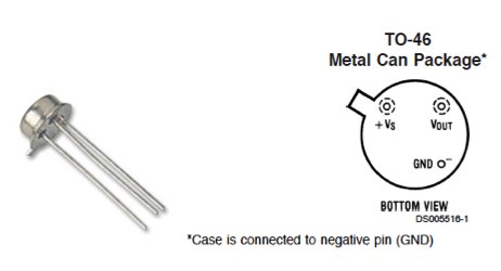
The LM35 series of temperature sensors are produced by National Semiconductor Corporation and are rated to operate over a -55 °C to 150°C temperature range. These sensors do not require any external calibration and the output voltage is proportional to the temperature. The scale factor for temperature to voltage conversion is 10 mV per °C. The LM35 series sensors come in different packages. The one I used is in a hermatic TO-46 transistor package where the metal case is connected to the negative pin (Gnd).
The measurement of negative temperatures (below 0°C) requires a negative voltage source. However, this project does not use any negative voltage source, and therefore will demonstrate the use of sensor for measuring temperatures above 0°C (up to 100°C).
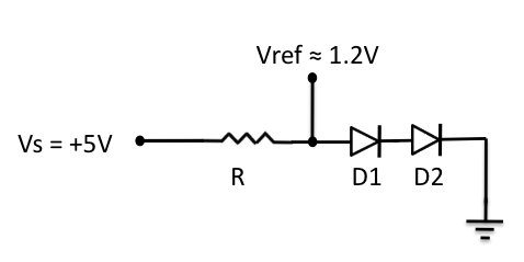
The output voltage from the sensor is converted to a 10-bit digital number using the internal ADC of the PIC16F688. Since the voltage to be measured by the ADC ranges from 0 to 1.0V (that corresponds to maximum temperature range, 100 °C), the ADC requires a lower reference voltage (instead of the supply voltage Vdd = 5V) for A/D conversion in order to get better accuracy. The lower reference voltage can be provided using a Zener diode, a resistor network, or sometime just simple diodes. You can derive an approximate 1.2V reference voltage by connecting two diodes and a resistor in series across the supply voltage, as shown below. As a demonstration, I am going to use this circuit in this project. I measured the output voltage across the two diodes as 1.196 V. The resistor R I used is of 3.6K, but you can use 1K too. The important thing is to measure the voltage across the two diodes as accurate as possible.
We need do some math for A/D conversion. Our Vref is 1.196 V, and the ADC is 10-bit. So, any input voltage from 0-1.196 will be mapped to a digital number between 0-1023. The resolution of ADC is 1.196/1024 = 0.001168 V/Count. Therefore, the digital output corresponding to any input voltage Vin = Vin/0.001168. Now, lets see how to get the temperature back from this whole process of converting sensor’s output to 10-bit digital number.
Assume, the surrounding temperature is 26.4 °C. The sensor output will be 264 mV (0.264 V). The output of ADC will be 0.264/0.001168 = 226. If we reverse this process, we have 226 from ADC and we can go back and find the temperature by using the sensor scale factor (10 mV/°C),
temperature = 226 * 0.001168 (V/Count) / 0.01 (V/°C) = 26.4 °C
If you want to avoid floating point math in your program, just use,
temperature = 226 * 1168 = 263968
While displaying this, you need to put a decimal at the fourth place from the left. So the calculated temperature is 26.3968°C, which is pretty close to the actual one. The difference is caused by quantization and rounding errors. In this project, we will display temperature accurate to one decimal place, i.e., we will divide the above number by 1000 to get 263. So the temperature will be displayed as 26.3 °C.
Once you have derived the temperature back in °C, you can convert it to °F using a simple equation,
temperature in °F = 9 x temperature in °C /5 + 32
In this case, the number you got for °C is scaled by 10 (263 for 26.3), you should use
temperature in °F = 9 x temperature in °C /5 + 320
Since, the number for °C may not be exactly divisible by 5 (such as 263 is not), you can further eliminate the floating point by scaling it one more time by 10. So the new equation will be,
temperature in °F = 9 x temperature in °C x 10 /5 + 3200
or, temperature in °F = 18 x temperature in °C + 3200 = 18 x 263+3200 = 7934
79.34 °F is equivalent to 26.3 °C. In this project, it will be displayed as 79.3 °F.
Circuit Diagram
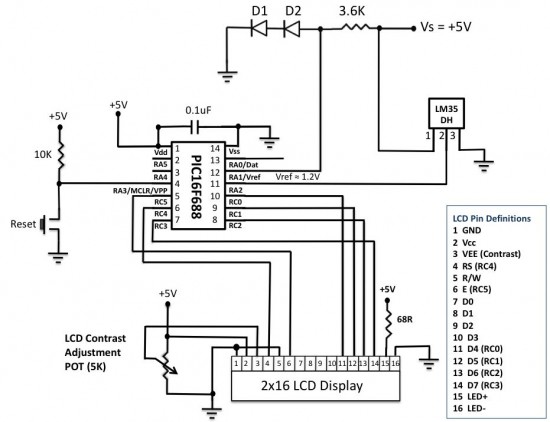
An external reference voltage to the internal ADC of PIC16F688 can be provided through RA1 I/O pin. The output from the LM35 sensor is read through RA2/AN2 ADC channel. The temperature is displayed on a 16×2 character LCD that is operating in the 4-bit mode. A 5K potentiometer is used to adjust the contrast level on the display. The detail circuit diagram is given below. Note that the PIC16F688 uses its internal clock at 4.0 MHz.
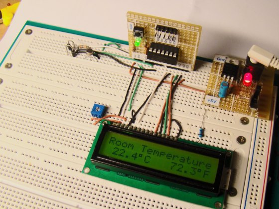
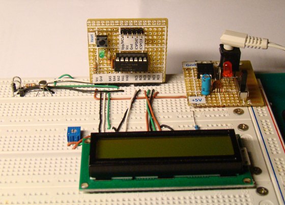
Circuit setup on the breadboard
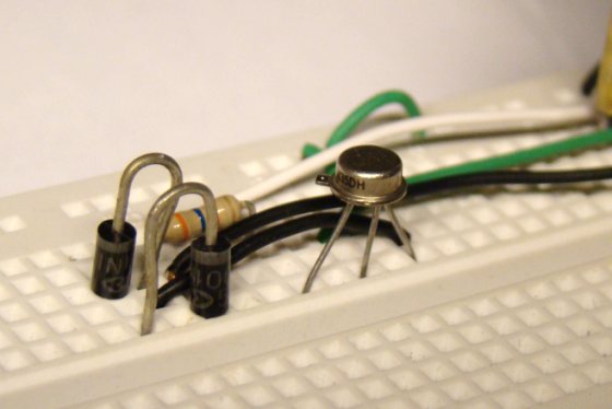
A closer look at the LM35DH sensor and the reference voltage circuit.
Software
Oscillator -> Internal RC No Clock
Watchdog Timer -> Off
Power Up Timer -> On
Master Clear Enable -> Enabled
Code Protect -> Off
Data EE Read Protect -> Off
Brown Out Detect -> BOD Enabled, SBOREN Disabled
Internal External Switch Over Mode -> Enabled
Monitor Clock Fail-Safe -> Enabled
You can set these fuses in the Edit Project window (Project-> Edit Project)
/* Digital Thermometer using PIC16F688 and LM35
Internal Oscillator @ 4MHz, MCLR Enabled, PWRT Enabled, WDT OFF Copyright @ Rajendra Bhatt November 8, 2010 */

// LCD module connections
sbit LCD_RS at RC4_bit;
sbit LCD_EN at RC5_bit;
sbit LCD_D4 at RC0_bit;
sbit LCD_D5 at RC1_bit;
sbit LCD_D6 at RC2_bit;
sbit LCD_D7 at RC3_bit;
sbit LCD_RS_Direction at TRISC4_bit;
sbit LCD_EN_Direction at TRISC5_bit;
sbit LCD_D4_Direction at TRISC0_bit;
sbit LCD_D5_Direction at TRISC1_bit;
sbit LCD_D6_Direction at TRISC2_bit;
sbit LCD_D7_Direction at TRISC3_bit;
// End LCD module connections
// Define Messages
char message0[] = "LCD Initialized";
char message1[] = "Room Temperature";
// String array to store temperature value to display
char *tempC = "000.0";
char *tempF = "000.0";
// Variables to store temperature values
unsigned int tempinF, tempinC;
unsigned long temp_value;
void Display_Temperature() {
 // convert Temp to characters
 if (tempinC/10000)
 // 48 is the decimal character code value for displaying 0 on LCD
 tempC[0] = tempinC/10000 + 48;
 else tempC[0] = ' ';
 tempC[1] = (tempinC/1000)%10 + 48; // Extract tens digit
 tempC[2] = (tempinC/100)%10 + 48; // Extract ones digit
 // convert temp_fraction to characters
 tempC[4] = (tempinC/10)%10 + 48; // Extract tens digit
 // print temperature on LCD
 Lcd_Out(2, 1, tempC);
 if (tempinF/10000)
 tempF[0] = tempinF/10000 + 48;
 else tempF[0] = ' ';
 tempF[1] = (tempinF/1000)%10 + 48; // Extract tens digit
 tempF[2] = (tempinF/100)%10 + 48;
 tempF[4] = (tempinF/10)%10 + 48;
 // print temperature on LCD
 Lcd_Out(2, 10, tempF);
}
void main() {
 ANSEL = 0b00000100; // RA2/AN2 is analog input
 ADCON0 = 0b01001000; // Connect AN2 to S/H, select Vref=1.19V
 CMCON0 = 0x07 ; // Disbale comparators
 TRISC = 0b00000000; // PORTC All Outputs
 TRISA = 0b00001110; // PORTA All Outputs, Except RA3 and RA2
 Lcd_Init(); // Initialize LCD
 Lcd_Cmd(_LCD_CLEAR); // CLEAR display
 Lcd_Cmd(_LCD_CURSOR_OFF); // Cursor off
 Lcd_Out(1,1,message0);
 Delay_ms(1000);
 Lcd_Out(1,1,message1); // Write message1 in 1st row
 // Print degree character
 Lcd_Chr(2,6,223);
 Lcd_Chr(2,15,223);
 // Different LCD displays have different char code for degree symbol
 // if you see greek alpha letter try typing 178 instead of 223
 Lcd_Chr(2,7,'C');
 Lcd_Chr(2,16,'F');
 do {
 temp_value = ADC_Read(2);
 temp_value = temp_value*1168;
 tempinC = temp_value/1000;
 tempinC = tempinC*10;
 tempinF = 9*tempinC/5 + 3200;
 Display_Temperature();
 Delay_ms(1000); // Temperature sampling at 1 sec interval
 } while(1);
}
Output
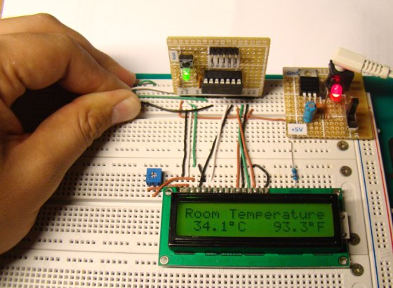
I took some pictures of the completed project displaying temperatures in both the scales.
Temperature goes up if you touch the sensor with your fingers
Accuracy of the measurement
The accuracy of the temperature measurement highly depends upon the stability of the reference voltage. If the reference voltage drifts from the value that we considered in our calculation, the measured temperature value could be significantly off from the actual value. Using a simple diode-resistor network for deriving a reference voltage may not be a very good idea, but the purpose of this project was to demonstrate the technique, not to come up with a commercial digital thermometer product. You can also try a Zener diode or a potentiometer to derive the reference voltage. Besides, the quantization error introduced by the 10-bit ADC, rounding numbers while doing the math, and the accuracy of the sensor itself within the desired range of temperature also affect the measurement output. Read the manufacturer’s datasheet for more details on the performance of the LM35 series sensor.
Update
This design has a little flaw. It uses a voltage drop across two diodes (? 1.2 V) as a reference voltage (Vref) for A/D conversion. However, the datasheet of PIC16F688 suggests to use Vref greater than 2.2 V to ensure 1-LSB accuracy in the A/D conversion. Therefore, I have re-written this project but this time using a MCP1525 device for creating a precise 2.5 V reference voltage. The new design is more precise and accurate in taking temperature measurements. Read “Revised version of LM35 based digital thermometer“.
|
|

hey, can I have the source code as well, please? I am using 3 nodes Adhoc wireless system with one node that is similar to your project.
Hello.
I am a B.tech 1st year student(cse branch)
I want to do this project with a little modification.I want to measure water temperature,along with air temperature using the same setup. Can u tell me which type of sensor is good for measuring water temperature?
I’m no expert in electronics, so please help me out, where is the power supply connected?
hi i want to design temperature measurement wireless sender and receiver circuits with infrared using lm35 sensor with avr microcotroller . please help me and show me circuit diagram and how to programming.
Please can you give me the C code for this project? am using PIC18F4520.
God bless you
CAn you help developing a 2 channal , indicator one input is thermocouple and othrer input is 0-5000mv
i need to write aclculation using thse two inputs and the result needs to be displayed and using a DAC need to out put in 4-20mA output.
what will be the minimum cost price
I need your help: I want sourccode
LM35 and sevenSegment with pic 16f877
thank you very much
hey can i have the source code as well please?
dear tem I need help from you how can I get code for control teperature “C” &”F” with LCD
thanks ,
regard,
Touqi
R-B,
Doubt 1
Here in this article in comment section you mentioned that “Yes, you are right. It won’t measure above 120 degree C. Thank you for the correction.”, what should be done to measure more than 120 deg, why it is linked with 1.2 voltage reference.
Doubt 2
If I take analog input from output of an OP amp (suppose a transducer signal is amplified by an op amp and op amp o/p is connected to A to D channel of PIC micro) what should be the reference voltage (say complete out put range of OP amp is 0 to 4000 mV) in that case what will be the ADCON0 register configuration, complete 5 Volt or less
Regards,
Akash
can you please tell me where can i buy this lcd display; lm 35 sensor and what kindey of diodes you use and them marks.
thank you
aljaž
Hi Raj!
What about 4 diodes in a series. It would make Vref 2.4V which is near from 2.2 VRef recommanded by the datasheet.
what do you think?
thank you!
marC:)
You can do that too.
i am working on a pic microcontroller based room temperature measurement project.
i tried to compile my code but i gave the error “demo limit”. can someone out there help me to compile the code to hex file if i send it out.
Thanks
Tolu
Pingback: LM35 Temperature Heat Sensor Integrated Circuit | Free pdf download | RoCkZzZ
Raj?
What is the purpose of the resistor here?
thank you very much!
marC:)
What if you select vdd as voltage reference??
thank you!
marC:)
HI Raj!
Where did you get the 1.2v ref?? how did you know that it took 1.2v ref?
why not 3v ref??
thank you!
marC:)
Voltage across two forward biased diodes is approx. 1.2V. You can try it yourself.
very great project………….can u tell me how much it’s total cost is …and can we run this C-lang program for PIC16f877a….reply
i wanna put a red n green led into condition of that temperature.instant of when temperature less than 23 degree and more than 28 degree celcius, led red is blinking and it’s as indicator for user taking a action.other that the range led green is on and it’s condition is good. i’m tried to put any if else condition,but it still has error..can u help me instant of a coding..?
hi, the work is good but for me am using ATMEGA8 and i want to measure negative temperature and my code is not working, pls what do you think i can do because using an operational amplifier is consuming my out put from the LM35
Hi R-B! I got 119 o C is it normal? what did i miss?
thank you!
marC:)
thanks:-) helped a lot in minor project
helped a lot in minor
Hello! Nice little project! 🙂
My mplab doesnt want to compile with PICC compiler.. 🙁
what suite of mplab do you use?
many thanks !:)
marC:)
The code written here is in mikroC compiler.
Same comment I left for the LM34DZ…There needs to be a resistor on the output to get the full range of measurement, otherwise you lose the ability to measure the low end.
sir .
plz send the coding for interfacing lm35 with 8051 to measure and display the temperature in degree
sir RB,
can u list down all the equipment that needed in this project, pls?
But when PICKit2 connection with the circuit, the PICKIT2 does not recognize device (PIC16F688).
But when I not connect the voltage Vref PICKit2 then PICKIT2 OK.
Help me.
Many Thank
If you want 100 C then you should use 10K resistor with diodes
HI PPT ARE NIT AVALABLE
Pingback: Electronics-Lab.com Blog » Blog Archive » Revised version of LM35 based digital temperature meter
@ R-B
The code for LCD is inside mikro C pro. Go to help and type LCD, you will get the initialization command for it.
Thanks
You may also like this
Nokia 3315 LCD base temperature meter using lm35
http://www.circuitvalley.com/2011/11/nokia-3315-lcd-based-temperature-meter.html
Hi
Sir,
i coudn´t find code for LCD Initialization in the code. how did you did it?
Thanks
Regards
Meley,
LCD initialization is done by Lcd_Init() function. It is a built-in routine of mikroC Pro for PIC compiler.
please could you kindly supply the circuit diagram of the new Vref = 5V and Vout through a non-inverting op-amp circuit and also what will be the calculations for finding the temperature?? please help thanks alot!
@Antonio Cesar
Did u check diode polarity?
@Antonio Cesar
Did u check diodes polarity?
Hello R-B, thanks for the excellent project!
I mounted the circuit and coding exaclty as in your website, however, I have the following problem: The ADC is reading fine however the Vref pin seems not working, I change the values and nothing happen.
The most funny is that when I use the HEX file that you attached in the website, it works perfect.
Do you have any hint?
Regards
Sir,
it is my final year project.I made the circuit as you have been made.But,the output of LCD display is not show.I used only LM35DZ instead of LM35DZ.The other thing is not changed.
@Pratim,
What do you mean by ‘LM35DZ instead of LM35DZ’?
Hi sir, i already solve the problem,actually the problem cause by the trimmer wiring connection ,i wrongly connect it,now it is ok ready…i also have make a pcb for this project using eagle cad and it is functioning good. Thank you very much for your help sir ( R-B,Supra )…
and i would suggest this website which is may usefull to others http://www.cytron.com.my.
@HobbyElectronicist,
In this crt, used 1N914 (maximun voltage is 100V).
If u r using 5V, look for maximun voltage that comes with voltage references.
@Jobarteh88,
There is tutorial on site:
http://www.mikroe.com/eng/chapters/view/14/chapter-1-world-of-microcontrollers/
@aaron,
U can used any specs of LCD with or w/out backlight such as 8×1, 16×1, 16×2 or 16×4, 20×1 or 20×2 or 20×4, or even 128×64 with or w/out touchscreen, etc. The max of LCD is 4 lines.
2) u can write ur own eepromn that comes with pic.
3) u can buy ePIC-KIT2 ISP Programmer & Debugger, but it is not clone.
Yes, it is compatible with pic16F and pic18F ONLY.
U can’t buy ICD2 clone such as pick2 clone. it will not work even if it is made in china. But u can get original made in china, But very expensive.
4) buy latest advantages that comes with features such glcd, ds18s20, servo, usb, etc that suit ur needed. The disadvantage is older model(wasting of money)
5) Yes, u can his(RB)hex file. In Mplab, that do for u so u get asm, mikroC, mikroBasic, pascal.
@ganesh,
If ur LCD comes with 16 pins w/out backlight, disconnected pin 15 and 16.
Also check solder bridge between pin to pin.
Check ur crt wiring.
Hi sir, i have built the circuit.but the problem is, it not showing anything ,when i adjust the trimmer the screen became dark in box shape.?plz help me sir,
@ganesh,
If the LCD shows all dark boxes, it means the display is not initialized. Either your circuit is not correct or the microcontroller is not running. Check the circuit carefully.
I rewired everything as showing above including didoes and resistor. And i got same result. The temperature is still fluctuated. Vref on RA1 is 0.28V.
I went thru google search and said it wouldn’t work with pic16f887 also can’t work with external.
I will have to switch to pic16F877 or pic18F4525 or dspic30F604013. If not i will move on to mmx7.
I got pic16F887, 8Mhz working. In LM35DZ, I leave out diodes and resistor. Here is code I did minor changed:
ANSEL = 0x04; // RA2/AN2 is analog input
AnselH = 0;
C1ON_bit = 0;
C2ON_bit = 0; // …
TRISA = 0x0D; //PORTA All Outputs, Except RA3 and RA2
TRISB = 0; // PortB as output
//
:
:
:
:
do
{
temp_value = ADC_Read(2) << 2;
temp_value = temp_value * 1168;
tempinC = temp_value / 1000;
tempinC = tempinC * 10;
tempinF = 9 * tempinC/5 + 3200;
Display_Temperature(); // Temperature sampling at 1 sec interval
Delay_ms(1000); // Temperature sampling at 1 sec interval
} while(1);
While I powered up. The temperature is changing fluctuated up and down. I got exactly room temperature 23 to 29C. How do i get Fixed temperature?
@supra,
Is your room temperature stable? What is your reference voltage for A/D conversion? How can I tell you what’s wrong with the code if you don’t show me your circuit diagram? And even the program you sent is not complete. What type of variables are tempinC and tempinF (float, int, long)? Send me these details at admin (at) embedded-lab.com so that I can answer your questions.
Thanks. I’m using pic16F887, but w/out using didoes D1 and D2 and 3.6K ohms. And I got room temperature 0.0c and 32.0F. Do u think i should add didoes and 3.6k ohms?
ASAP!
It depends on what reference voltage are you using for A/D conversion. The diodes and the resistor in my circuit provides an external reference voltage of 1.2 V.
Thanks for the clarification RB. Great job!
Hello RB,
what happen if i used the internal 5v ref & excluding the 1.2v external vref?
As i only have some mcp9700 which max output is 1.7v.
Whats the max temperature i can get with 1.7v?
@Meguitarist,
You can use +5 V as reference for A/D conversion of signal from MCP9700. It will decrease the resolution of ADC as the maximum input voltage to ADC channel is far less than +5 V. But that would work. You will be able measure the entire range of the temperature that could be measured by MCP9700.
sir,i hav not tried anything on designing and placing of components on a board but this project is my first so sir,how do i go about designing this particular project as a beginner.
it is my first time of visiting this site nevertheless,this work is very impressive.this is actually what i am working on as my final year project.i would appreciate if you guys could send me materials on how to lay components on PCB.More grace to your elbow.
Thanks for posting a nice blog like this. It is a great project to do, with those instructions having the photos it’ll be a help for those beginners on this field of work.
Sir, I have developed an 89c51 based system in which adc0804 take the current temperature of LM35 and display it on a 2X16 LCD display. Now the problem is that it only displays positive temperature.It cannot display -ve temperature.My program is in c51.Please help me out how to do that.Thanks
hi
kindly send me the details about the data conversion in 16f877A, like binary to decimal and hex to decimal
Pingback: Trying to create a Digital Thermometer
1.also, can you tell me what particular specs of LCD should i buy?
2.Can you also add a feature of logging temp. data on its own circuit and retrievable later from the PC?
3.if i buy this clone “ePIC-KIT2 ISP Programmer & Debugger”
or “PIC In-Circuit Debugger and Programmer (ICD2 Clone)” from the website http://www.e-gizmo.com/KIT/ePIC-KIT2.htm, is it compatible in this project?
4. what is the advantages and disadvantages of these two? many programmer kits are confusing me.
5. can i use your Hex file and also download MPLAB with this kit?
sorry if i have a wrong question, i’m still studying this PIC stuff…
Hi, i haven’t done any PIC project yet, but I’m reading tutorial lessons now. however as much as i would like to do the project, i am also hesitant because as i read the readers’ comments, this particular project suggests for a modification particularly for the reference voltage.
can somebody provide a revised version, please?
also, can somebody add crtain feature to this project such as:
1. i can program the circuit to send a positive signal for a relay when the temperature reaches above 30 and below 15 degrees centigrade.
Hi, would you please be able to tell me what diodes you used to get the reference voltage? I’m a little confused about how to derive a suitable reference voltage using the two diodes.
Thank you.
These are just normal Silicon diodes that have forward biased voltage of approximately 0.6 V. But I won’t recommend doing this as I realized later that the Vref for PIC16F688 must be over 2 V (read other comments). I would rather suggest to use Vref = 5 V and amplify the LM35 output with a non-inverting Op-amp circuit.
hi! do you have a pic programer circuit for that? and the pic programmer program also. TIA
hi
Diodes that use
.
good project
Dear sir;
where do i get the details of the project to start developing it. i try to check for more information about the project to try building it myself but basically i can only view the theory and introduction… can u help me with its detail like the programming, the list of components and some guides to building the project. thanks for the post.
Hello there,
You use a Vref+ of 1,2V, but the datasheet says the 16f688 can only use a minimum Vref+ of 2V. How did you solve this problem?
Thanks,
Cooney
Thanks for sharing your projects.
The PIC16F688 data sheet (pg.155) says to ensure 10b accuracy Vref must be at least 2.5V.
Max,
I missed that part, thank you for pointing this. This is another limitation of this project. But if you increase Vref to 2.5 V, the resolution of ADC will go down (means more uncertainty in the measurement) as the output from LM35 sensor can swing only up to 1.5 V. One solution could be to use an active device to scale the output voltage from the LM35 sensor, but that will add further complexity.
Thank you.
Pingback: Rounding Off float value in PIC C
When the above C code is compiled with MikroC, an equivalent assembly code is generated. You can see the assembly code by clicking on View Assembly from the Project menu.
A job well done.
Congratulations for the superb projects.
I need the same coding done in Assembly language. any assistance.
Thanks.
Yes, you are right. It won’t measure above 120 degree C. Thank you for the correction.
Hello Mr. Raj,
If I’m not mistaken, with a 1.2 vdc reference we have up to 120 degrees Celsius, correct me if I’m wrong.
Congratulations with this site, keep up the good work.
Pingback: Electronics-Lab.com Blog » Blog Archive » Measuring temperature using LM35 Sensor
Nice work! I will feature it as well in pcbheaven.com
Check the link for the datasheet you provide for the LM. You should include the “http://” otherwise it searches in the current directory 😉
I like the way you documents your projects! Keep up the good work.
Thanks for pointing that. I corrected it now.