Revised version of LM35 based digital temperature meter
|
|
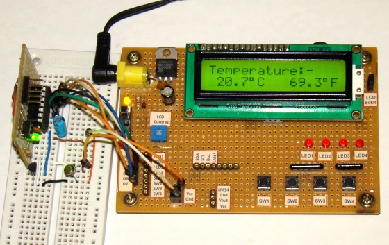
This is a revised version of my LM35 based digital thermometer project that I posted last year. Although it is one of the simplest projects, it is very popular among newbies who are just starting to learn microcontrollers. There was a little flaw in the original project as pointed by some readers. I was using a 1.2 V reference for A/D conversion with PIC16F688 microcontroller. However, the PIC16F688 datasheet says Vref should be equal to or higher than 2.2 V to ensure 1 LSB accuracy of A/D conversion. Here, I am rewriting the same project but this time I am using a MCP1525 IC to generate a precise 2.5 V reference for A/D conversion. This will improve the accuracy of temperature measurements.
Theory
The LM35 series of analog temperature sensors are produced by National Semiconductor Corporation and are rated to operate over a -55 °C to 150 °C temperature range. These sensors do not require any external calibration. The output voltage is proportional to the temperature, and the temperature-to-voltage conversion factor is 10 mV per °C. The sensor does not have any DC offset output voltage (which means the output is 0V at 0 °C temperature) and therefore, a negative voltage source is required in order to measure temperatures below 0 °C. For simplicity, the setup shown here is made to measure temperatures above 0 °C only. The PIC16F688 microcontroller reads the analog output voltage from the sensor through one of its ADC channel and derives the temperature information out of it.
For the maximum temperature value of 150 °C, the output voltage of the sensor would be 150 x 10 mV = 1. 5 V. If we use Vref = 5.0 V (power supply voltage) for A/D conversion, the resolution would be poor as the input signal goes only up to 1.5 V. Besides, if the supply voltage is not stable, it won’t be a good idea to use it as Vref for A/D conversion. Using a lower and more stable Vref voltage can improve both the resolution and the accuracy of A/D measurements. However, the datasheet of PIC16F688 microcontroller recommends to use reference voltage above 2.2 V to ensure 1 LSB accuracy of A/D conversion. The MCP1525 IC from Microchip provides a precise output voltage of 2.5 V, which could serve this purpose. This device is also available in TO-92 package, and therefore, it can be wired on a breadboard too.
Circuit diagram
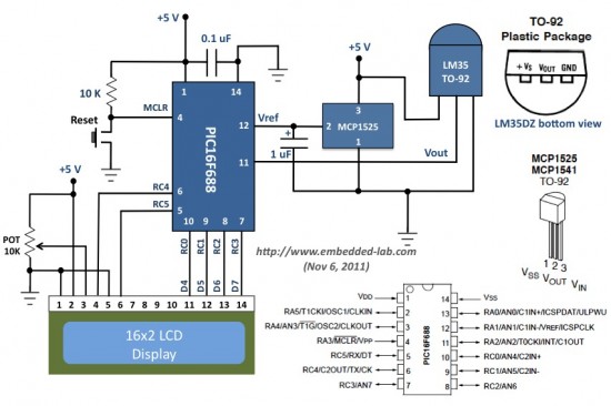
The revised circuit diagram of the project is shown below. All the connections remain the same, except the two diodes and a resistor in the original circuit are replaced by a MCP1525 device.
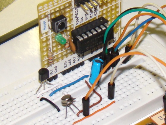
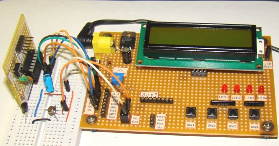
The whole setup of this project is shown below. For illustrative purpose, I am using the LCD display from my I/O board project here. Don’t get confused with all the LEDs and tact switches on the board, they should be disregarded. I am only using the LCD part of it.
Software
With Vref = 2.5 V, the resolution of 10-bit A/D conversion would be 2.5/1024 ? 2.44 mV/count. Which means,
Resolution of temperature measurement = 2.44 mV/(10 mV/°C) = 0.244 °C
I/P analog voltage = 2.44 x 10-bit count (mV)
Measured temperature = I/P voltage (mV)/(10 mV/°C) = 2.44 x 10-bit count/10 (°C)
Or, T (°C) = 0.244 x 10-bit Count
Floating point math can be avoided in programming to simplify the arithmetic. The complete program (source and HEX files) written in mikroC Pro for PIC can be downloaded from the following link.
Download mikroC source and HEX files
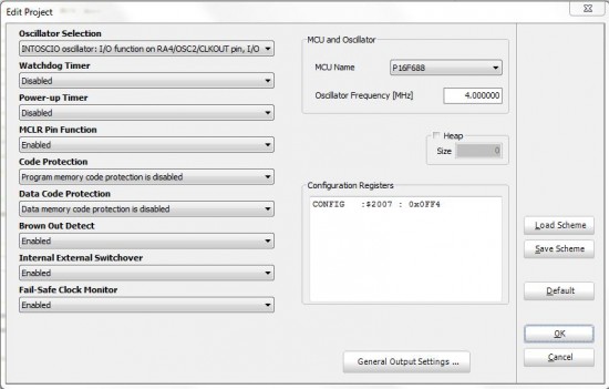
The following snapshot of the Project Edit window from mikroC editor shows the configuration bit setting for this project.
Additional Tip
The LM61 sensor is more convenient to use for measuring negative temperatures. Unlike LM35 (which has zero DC offset), the LM61 sensor has a DC offset of 600 mV, which allows reading negative temperatures without the need for a negative supply.
|
|

Hi, would u mind sharing the code using MPLAB IDE and pic16f877A ??
hi raj.
can you please post the source code for this project using MPLABX and pic18f26k22
pleaaaaaaaaaaaaaaaaas
can u please post the source code for this project using MPLABX and pic18f26k22
hi. is LM35 suitable to be used for measuring soil temperature? and can you email me your hex code and circuit diagram?
I have already obtained a programmed PIC using the data from your previous version, will it work on the revised version?
dear sir,
can u send the micro c programme of the this circuit too.(as your first project).(not hex file)
i hope a kind reply.
daminda
G
pls iwant u to help me with circuit diagram of solar incubator using PIC18F4550
Hi
I so happy to that your project done well. but i don’t understand about
why
temp_value = temp_value*244; what is number of 244?
tempinC = temp_value/10;
i hope you can explain me.
thank you so much.
Hi Raj,
I have tried your circuit and is working perfectly gud. but i am wondering, wt will actually happened when the temperature goes below 0 degrees, if i will be using LM35. you stated that the LM61 is gud for -ive values but i think we have to make some changes in the program of the controller to interface LM61 instead of LM35.
i program the controller in Hitech C compiler. so i hv no idea about the mikroC. also i dont have much experience to program 16f688 controller in Hitech C. I tried to program 16f688 but i cannot able to interface the LCD with 16f688 through Hitech C compiler. i am using ready-made LCD program for 16F877a controller from the website http://www.microchipc.com. but after making changes to the program for 16f688 i failed.
Please give me some suggestions. if you have any idea about Hitech C or tell me what changes i hv to do in your program in mikroC to interface LM61. Thanks in advance.
hi,
i made your circuit.it is working in good condition.but the problem is displaying value is alwase four celcous grater than real value.how can i reduse that.
daminda
Hello!
I built a thermometer, but the temperature is always hopping. Over those things again, I measured everything but I could not find fault. If I remove the PIC, the temperature is not hopping after measuring the output of the LM35. What could be the problem? The PIC program is installed again but it did not solve. Thank you for your help in advance.
Video: http://www.youtube.com/watch?v=v90aGrH0vo4&feature=youtu.be
That is interesting. How are you powering your circuit?
Hi Raj,
I used ADC value in an equation or formula which give result in “negative value such as -10.5”. How I can display this negative value (-10.5) on LCD using MikroC Pro. If possible, please email example.
Thank you.
hello
sir is it possible that you could add a code for this
project that will turn on/off a relay at preset value.
i’d like to use this for my egg incubator projet..
if its ok.
thanks..
Hi Raj!
Let’s say i put 4 diodes as voltage reference. it’s now 1. so the VRef now is 2.4 v
so it is good.
don’t you think?
thank you!
marC:)
if i want to connect it with pc, what is the possible way to run this project via PC?
Hi, I do not understand why adding 48 in the operation, I find no logic. Thanks..
Decimal 48 is added to each integer to convert it to ASCII character. ASCII code of 0 is 48, 1 is 49, 2 is 50 and so on.
Gracias !!!
me sirvio de lujo!!
Thanks!!
It was very useful!!
i wanna put a red n green led into condition of that temperature.instant of when temperature less than 23 degree and more than 28 degree celcius, led red is blinking and it’s as indicator for user taking a action.other that the range led green is on and it’s condition is good. i’m tried to put any if else condition,but it still has error (just 1 led is on)..can u help me instant of a coding..?
next,in my proteous cant find out MCP1525 device,can i use other devices?
and for your A Digital temperature meter using an LM35 temperature sensor project,went i run into proteous,value from LM35 is different with value in LCD.it’s because of voltage reference?
my jumpers was shorted off!!!
it’s really handy, a great gift for my appartment
thank you so much!
have a great success!
marC:)
Hi,
Have you seen this ( MikroC Pro Help ) :
ADC_Read()
unsigned ADC_Read(unsigned short channel);
Note : This function doesn’t work with the external voltage reference source, only with the internal voltage reference.
It’s true that ADC_Read() by default uses the internal reference voltage which is the supply voltage. But if you configure ADCON0 appropriately in your main program, the ADC_Read can be made to use the external reference voltage. That’s why I have ADCON0 = 0b01001000; in my program. This is my experience.
Pingback: Digital temperature meter | WORLD OF ELECTRO
hi
i forgot to tell you one thing
When i start the simulation with proteus gives me on error
“Configuration word bits CP(A) (bits 4-5, 0b11) and CP(B)(bits12-13,0bb00) should be indentical.
Please help me
Hi
Im using a PIC16F877 insted PIC16F688
But when i make a simulation on Proteus
Only show
Temperature:-
c f
I conect vout to pin 4(on pic16f877) and vref ( pin 12 on pic16f688 ) to pin 3 ( on pic16f877)
So what i did wrong ?
Sorry bad englih
U should read the data sheets of both controllers. the program written for 16f688 is different then the program written fot 16f877. this is because of the registers configuration
i’am really appreciate for what u have doing 🙂
i think i wanna try to use your program for my FYP
but i have few question:
1)i need to measure water temperature..is LM35 possible to do this?if not,what type of temperature sensor i need to use?
2)then,when the sensor read the temperature,it will control the heater (whether ON/OFF) in order to maintain the water temperature at 37 deg celcius..can u give me some idea how to do this?
TQ 🙂
Hey Raj,
If i add MCP1525 and connected to vref(pin 12), it will prevent fluctuation? Where did u get mcp1525? It is not on ebay.
Salaam,
supra
supra,
Can you tell me in detail about the amount of fluctuation you are noticing? Describe in detail of your project so that I could help you.
Hi Raj,
Does ur temperature changed inside room? How do u prevent temperature changing. I built the u posted last yr, but the temperature is still changing.
Supra,
I don’t see any significant fluctuation in the output.
HI, FOR LINEAR (0.1C OR 0.1F ) RAISING IN DISPLAY WHAT I HAVE TO DO?
IS THERE IS ANY FORMULA ?
Can U Please Tell Me what are the alternative Microcontrollers That I can Use In This Circuit? .. :S
Ali El-Dean,
You can use any other microcontroller with ADC channel. You have to write a firmware for the microcontroller you choose.
Will it be possible to use LM336Z 2.5V Reference from National Semiconductor for this Project, I have a hard time finding the MCP1525
heres the data sheet for LM336Z
http://www.futurlec.com/Datasheet/Linear/LM336Z-25.pdf
@Zeraphine,
Yes, you can use LM336Z 2.5V instead of MCP1525.
Can I possibly make this circuit work in a PIC16F877A?