Measurement of temperature and relative humidity using DHT11 sensor and PIC microcontroller
|
|
Measurement and control of temperature and relative humidity finds applications in numerous areas. These days devices are available which have both temperature and humidity sensors with signal conditioning, ADC, calibration and communication interface all built inside them. The use of such smart sensors greatly simplify the design and reduces the overall cost. We discussed in past about Humidity and temperature measurements with Sensirion’s SHT1x/SHT7x sensors. These sensors are capable of measuring both temperature and relative humidity and provide fully calibrated digital outputs. While SHT1x/SHT7x are very accurate sensors, they are still expensive for hobbyists use. This articles discusses the DHT11 sensor which also provides calibrated digital outputs for temperature and humidity but is relatively lot cheaper than the Sensirion sensors. The DHT11 sensor uses a proprietary 1-wire protocol which we will be exploring here and implementing with the PIC16F628A microcontroller that will receive the temperature and humidity values from the sensor and display them on a 16×2 character LCD.

Interfacing DHT11 sensor with PIC16F628A
About DHT11 sensor
The DHT11 sensor comes in a single row 4-pin package and operates from 3.5 to 5.5V power supply. It can measure temperature from 0-50 °C with an accuracy of ±2°C and relative humidity ranging from 20-95% with an accuracy of ±5%. The sensor provides fully calibrated digital outputs for the two measurements. It has got its own proprietary 1-wire protocol, and therefore, the communication between the sensor and a microcontroller is not possible through a direct interface with any of its peripherals. The protocol must be implemented in the firmware of the MCU with precise timing required by the sensor.

DHT11 sensor comes in a single row 4-pin package
The following timing diagrams describe the data transfer protocol between a MCU and the DHT11 sensor. The MCU initiates data transmission by issuing a “Start” signal. The MCU pin must be configured as output for this purpose. The MCU first pulls the data line low for at least 18 ms and then pulls it high for next 20-40 ?s before it releases it. Next, the sensor responds to the MCU “Start” signal by pulling the line low for 80 ?s followed by a logic high signal that also lasts for 80 ?s. Remember that the MCU pin must be configured to input after finishing the “Start” signal. Once detecting the response signal from the sensor, the MCU should be ready to receive data from the sensor. The sensor then sends 40 bits (5 bytes) of data continuously in the data line. Note that while transmitting bytes, the sensor sends the most significant bit first.

"Start" and "Response" signals
The 40-bit data from the sensor has the following structure.
Data (40-bit) = Integer Byte of RH + Decimal Byte of RH + Integer Byte of Temp. + Decimal Byte of Temp. + Checksum Byte
For DHT11 sensor, the decimal bytes of temperature and humidity measurements are always zero. Therefore, the first and third bytes of received data actually give the numeric values of the measured relative humidity (%) and temperature (°C). The last byte is the checksum byte which is used to make sure that the data transfer has happened without any error. If all the five bytes are transferred successfully then the checksum byte must be equal to the last 8 bits of the sum of the first four bytes, i.e.,
Checksum = Last 8 bits of (Integer Byte of RH + Decimal Byte of RH + Integer Byte of Temp. + Decimal Byte of Temp.)
Now lets talk about the most important thing, which is signalling for transmitting “0” and “1”. In order to send a bit of data, the sensor first pulls the line low for 50 ?s. Then it raises the line to high for 26-28 ?s if it has to send “0”, or for 70 ?s if the bit to be transmitted is “1”. So it is the width of the positive pulse that carries information about 1 and 0.

Timing difference for transmitting "1s" and "0s"

Start, Response and Data signals in sequence
At the end of the last transmitted bit, the sensor pulls the data line low for 50 ?s and then releases it. The DHT11 sensor requires an external pull-up resistor to be connected between its Vcc and the data line so that under idle condition, the data line is always pulled high. After finishing the data transmission and releasing the data line, the DHT11 sensor goes to the low-power consumption mode until a new “Start” signal arrives from the MCU.
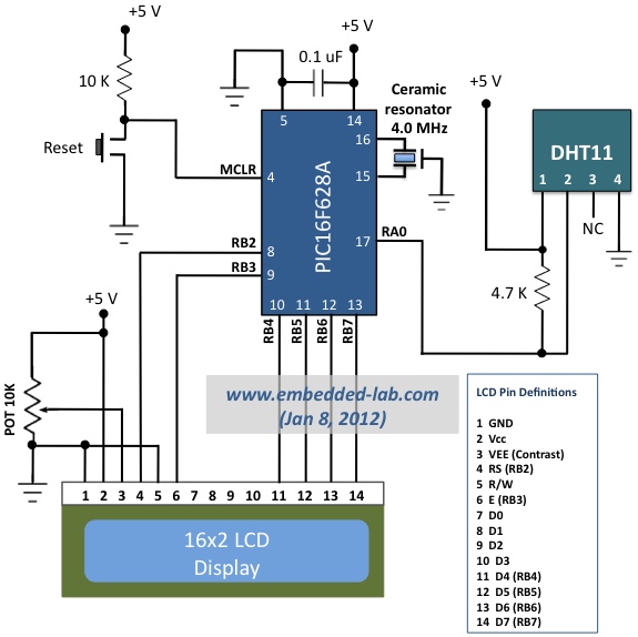
Circuit diagram
Here is the circuit diagram showing the DHT11 sensor and a HD44780-based character LCD interfaced to the PIC16F628A microcontroller. The microcontroller runs at 4.0 MHz clock using an external resonator connected between OSC1 (16) and OSC2 (15) pins. The use of 4.0 MHz clock makes the timing calculation easier as 1 machine cycle becomes 1 ?s. The timing information will be used to calculate the width of the received data pulse from the sensor so that we could identify if it is carrying a 1 or 0.

Circuit connections for PIC16F628A and DHT11 sensor
The following pictures show the circuit setup on a breadboard. Don’t get confused with the four LEDs and tact switches shown on the perforated board. They have nothing to do with this project. They are there because I am using my DIY Experimenter’s I/O board for the LCD part of this project. Similarly, I am using my 18-pin PIC16F board for easy prototyping with the PIC16F628A microcontroller.

Complete setup of the circuit

PIC16F628A module and the DHT11 sensor are plugged into the breadboard
Software
Writing a software for DHT11 sensor is little more challenging than the hardware part because of the timing conditions for 1s and 0s. I have written sub-routines in mikroC Pro for PIC for initializing the DHT11 sensor and reading the 40-bit of data in sequence. I have used Timer2 module to keep track of the width of the received data pulse, which is required to identify if the received bit is 1 or 0. When a low-to-high pulse is detected at the beginning of any data bit, TMR2 is cleared and turned ON. Since the clock frequency used here is 4.0 MHz, the TMR2 increments by 1 in every 1 ?s. The TMR2 is stopped whenever the data pulse is low again. The value of the TMR2 register gives you the the width of the data pulse in ?s. I am using 40 ?s as the threshold for identifying 0 and 1. If the TMR2 is greater than 40, it means the received bit is 1, else it is 0. Here is the complete source code written in mikroC Pro for PIC. It can be easily adapted to any other platform, but remember that if you are using a different clock frequency you should have to modify the timer operation accordingly.
// LCD module connections sbit LCD_RS at RB2_bit; sbit LCD_EN at RB3_bit; sbit LCD_D4 at RB4_bit; sbit LCD_D5 at RB5_bit; sbit LCD_D6 at RB6_bit; sbit LCD_D7 at RB7_bit; sbit LCD_RS_Direction at TRISB2_bit; sbit LCD_EN_Direction at TRISB3_bit; sbit LCD_D4_Direction at TRISB4_bit; sbit LCD_D5_Direction at TRISB5_bit; sbit LCD_D6_Direction at TRISB6_bit; sbit LCD_D7_Direction at TRISB7_bit; sbit Data at RA0_bit; sbit DataDir at TRISA0_bit; char message1[] = "Temp = 00.0 C"; char message2[] = "RH = 00.0 %"; unsigned short TOUT = 0, CheckSum, i; unsigned short T_Byte1, T_Byte2, RH_Byte1, RH_Byte2; void StartSignal(){ DataDir = 0; // Data port is output Data = 0; Delay_ms(25); // Low for at least 18us Data = 1; Delay_us(30); // High for 20-40 us DataDir = 1; // Data port is input } unsigned short CheckResponse(){ TOUT = 0; TMR2 = 0; T2CON.TMR2ON = 1; // Start TMR2 while waiting for sensor response while(!Data && !TOUT); // If there's no response within 256us, the Timer2 overflows if (TOUT) return 0; // and exit else { TMR2 = 0; while(Data && !TOUT); if (TOUT) return 0; else { T2CON.TMR2ON = 0; return 1; } } } unsigned short ReadByte(){ unsigned short num = 0, t; DataDir = 1; for (i=0; i<8; i++){ while(!Data); TMR2 = 0; T2CON.TMR2ON = 1; // Start TMR2 from 0 when a low to high data pulse while(Data); // is detected, and wait until it falls low again. T2CON.TMR2ON = 0; // Stop the TMR2 when the data pulse falls low. if(TMR2 > 40) num |= 1<<(7-i); // If time > 40us, Data is 1 } return num; } void interrupt(){ if(PIR1.TMR2IF){ TOUT = 1; T2CON.TMR2ON = 0; // stop timer PIR1.TMR2IF = 0; // Clear TMR0 interrupt flag } } void main() { unsigned short check; TRISB = 0b00000000; PORTB = 0; TRISA = 0b00100001; CMCON = 7; INTCON.GIE = 1; //Enable global interrupt INTCON.PEIE = 1; //Enable peripheral interrupt // Configure Timer2 module PIE1.TMR2IE = 1; // Enable Timer2 interrupt T2CON = 0; // Prescaler 1:1, and Timer2 is off initially PIR1.TMR2IF =0; // Clear TMR INT Flag bit TMR2 = 0; Lcd_Init(); Lcd_Cmd(_Lcd_Clear); Lcd_Cmd(_LCD_CURSOR_OFF); do { Delay_ms(1000); StartSignal(); check = CheckResponse(); if (!check) { Lcd_Cmd(_Lcd_Clear); Lcd_Out(1, 1, "No response"); Lcd_Out(2, 1, "from the sensor"); } else{ RH_Byte1 = ReadByte(); RH_Byte2 = ReadByte(); T_Byte1 = ReadByte(); T_Byte2 = ReadByte(); CheckSum = ReadByte(); // Check for error in Data reception if (CheckSum == ((RH_Byte1 + RH_Byte2 + T_Byte1 + T_Byte2) & 0xFF)) { message1[7] = T_Byte1/10 + 48; message1[8] = T_Byte1%10 + 48; message1[10] = T_Byte2/10 + 48; message2[7] = RH_Byte1/10 + 48; message2[8] = RH_Byte1%10 + 48; message2[10] = RH_Byte2/10 + 48; message1[11] = 223; // Degree symbol Lcd_Cmd(_Lcd_Clear); Lcd_Out(1, 1, message1); Lcd_Out(2, 1, message2); } else{ Lcd_Cmd(_Lcd_Clear); Lcd_Out(1, 1, "Checksum Error!"); Lcd_Out(2, 1, "Trying Again ..."); } } }while(1); } |
You can also simplify the ReadByte subroutine without using the Timer2 module. The following version of ReadByte subroutine works equally well. Once the data pin is detected high, wait for 40 ?s and check the data line again. If it is still high, it is 1, else 0.
unsigned short ReadByte(){
  unsigned short num = 0, t;
  DataDir = 1;
  for (i=0; i<8; i++){
   while(!Data);
   Delay_us(40);
   if(Data) num |= 1<<(7-i);
   while(Data);
   }
  return num;
}
Download complete source code and HEX files
Output
The accuracy of DHT11 is not as good as Sensirion’s SHT1X/7X series sensors, but it provides an easy and cheap solution to hobbyists for measuring relative humidity and temperature in parallel using a single device, which is sometime required in certain applications such as calculating the dew point.

Temperature and relative humidity measured by DHT11 sensor
|
|
The integration of humidity and temperature sensors into the same device has not only reduced the costs but also allowed for greater convenience in usage and transport of the device into the fields.
Thanks for you , you are creative
Did anyone know how to get rid of ‘no response from the sensor’ ??
I am using dht11 with lpc 2148 please provide code for it
Pingback: [PIC] Schema DHT11 avec pic 18f4550
can you send me code for PIC 16F877 and also that is interfacing with I2c lcd 20×4 display.
hey can you send me code for reading dhT11 para meter in PIC16F877 and also that cant transfer data to lcd using i2c.
send me the the port connection detail ,too. please it is urgent
hi! I need to create this program for a PIC16F877A,and could you please show me the circuit if I can use the same one as well.
I would like to receive your communications related to Embedded Lab
Hi, how are you . I congratulate you on your work. I have a problem. you can help me. to simulate it in PROTEUS I do not have any value above shows …
Sir, plz help me out. I have been using the provided hex file and using proteus 8 for this DHT11 interfacing. But it is showing no response from sensor. Could you plz give me its solution as early as possible. I think it is resonaror fault. If possible, plz send me design file.
regards.
Hi there,
i am making this project with at89c51 the can any one tell me this source code is right…?
MOV P1,#0FFH
RD BIT P2.0
WR BIT P2.1
INTR BIT P2.2
MYDATA EQU P1
MOV P1,#0FFH
SETB INTR
BACK: CLR WR
SETB WR
HERE: JB INTR,HERE
CLR RD
MOV A,MYDATA
ACALL CONVERSION
ACALL DATA_DISPLAY
SETB RD
SJMP BACK
CONVERSION:
MOV B,#10
DIV AB
MOV R7,B
MOV B,#10
DIV AB
MOV R6,B
MOV R5,A
RET
DATA_DISPLAY:
MOV P3,R7
ACALL DELAY
ACALL DATAWRT
MOV P3,R6
ACALL DELAY
MOV P3,R5
ACALL DELAY
DELAY: MOV R5,#0FFH
AGAIN: DJNZ R5,#AGAIN
RET
COMNWRT: MOV P0,A
CLR P3.0
CLR P3.1
SETB P3.2
ACALL DELAY
CLR P0.5
RET
DATAWRT: MOV P0,A
SETB P3.0
CLR P3.1
SETB P3.2
ACALL DELAY
CLR P3.2
RET
did u complete your this project??
Hello. Thanks for a nice project! Does someone have a PCB designed and could share it?
Jeffo,
You can buy a kit here with LED displays instead of LCD.
https://www.tindie.com/products/rajbex/pre-order-trh-meter-kit-3/
I am PIC hobbykits.I am thinking how if I just want the LCD to display temp C and humidity % in 3 seconds and then put the LCD into Sleep mode until the PIC16F628A wake up by pin 4 MCLR reset for power saving purpose.What addition source code need to add to the above programming code.Please advice.Thanks.
Thanks for sharing this, It saved me a lot of time. I had two sensors bought at dx.com, a pic16f628a and an old 4.33619 mhz crystall laying around build this :). Modified the code so that it also sends the strings over the uart. I’ve got an old kobo glo ereader with a broken screen which collects the data and sends it to my stbox from which i read it with my phone so i don’t have to go down to the cellar to check 😀
can you help me to add max232 to temperature humidity measuring project .best regards
I am using MPLAB IDE v8.63 can i just copy the code and use it??
Pingback: DHT22
plz i want to ask about: in: message1[7] = T_Byte1/10 + 48;
what’s the +48 for?? i didn’t understand the use of +48 thxxx
The use of +48 is changing from decimal to ASCII in oder to display on LCD, bro!
Hi there, can someboby help me modify the code?I want to add another DHT11 sensors for my project.I need two sensors for measuring two diferent spots. all replies on vanco@azet.sk.thanks
hi,
i want to work whit DHT11 but on pic 18f45k22.
i need a code or tuturial for this pic
Thanks
HI FRIEND ,I tried to make your code with the 18F452 ,but the sensor doesen’t response ,please help me
sbit Data at LATB2_bit;
sbit DataDir at TRISB2_bit;
unsigned short TOUT = 0, CheckSum, i;
unsigned short T_Byte1, T_Byte2, RH_Byte1, RH_Byte2, tmp, HM;
void StartSignal(){
DataDir = 0; // Data port is output
Data = 0;
Delay_ms(25);
Data = 1;
Delay_us(30);
DataDir = 1; // Data port is input
}
unsigned short CheckResponse(){
TOUT = 0;
TMR2 = 0;
T2CON.TMR2ON = 1; // start timer
while(!Data && !TOUT);
if (TOUT) return 0;
else {
TMR2 = 0;
while(Data && !TOUT);
if (TOUT) return 0;
else {
T2CON.TMR2ON = 0;
return 1;
}
}
}
unsigned short ReadByte(){
unsigned short num = 0, t;
DataDir = 1;
for (i=0; i 200) num |= 1< 40us, Data is 1
}
return num;
}
void interrupt(){
if(PIR1.TMR2IF){
TOUT = 1;
T2CON.TMR2ON = 0; // stop timer
PIR1.TMR2IF = 0; // Clear TMR0 interrupt flag
}
}
void main() {
unsigned short check;
ADCON1=0x06;
TRISB = 0;
TRISA0_bit =1;
TRISD = 0;
TRISC=0;
CCP1CON=0;
CCP2CON=0; // configure pins as input
INTCON.GIE = 1; //Enable global interrupt
INTCON.PEIE = 1; //Enable peripheral interrupt
// Configure Timer2 module
PIE1.TMR2IE = 1; // Enable Timer2 interrupt
T2CON = 0; // Prescaler 1:1, and Timer2 is off initially
PIR1.TMR2IF =0; // Clear TMR INT Flag bit
TMR2 = 0;
LATB0_bit=1;
Delay_ms(300);
LATB0_bit=0;
do {
Delay_ms(1000);
StartSignal();
check = CheckResponse();
if (!check) {
LATB1_bit=1;
Delay_ms(300);
LATB1_bit=0;
}
else{
RH_Byte1 = ReadByte();
RH_Byte2 = ReadByte();
T_Byte1 = ReadByte();
T_Byte2 = ReadByte();
CheckSum = ReadByte();
LATB1_bit=1;
// Check for error in Data reception
if (CheckSum == ((RH_Byte1 + RH_Byte2 + T_Byte1 + T_Byte2) & 0xFF))
{
LATB0_bit=1;
Delay_ms(300);
LATB0_bit=0;
tmp= T_Byte1/10 +T_Byte1%10 +T_Byte2/10;
HM= RH_Byte1/10 + RH_Byte1%10 +RH_Byte2/10;
}
else{
RB1_bit=1;
Delay_ms(300);
LATB1_bit=0;
}
}
}while(1);
}
if (CheckSum == ((RH_Byte1 + RH_Byte2 + T_Byte1 + T_Byte2) & 0xFF))
Just want to ask, why need to put & 0xFF?
sir i want to use dht11 with 8051 ,will u plz help me
I have done one, please contact me
Hello! I am working on dht11 and at89s51, could you help me?
reply me ainurka_bolat@mail.ru
Sir, can you please share with me the interface of dht11 and 8051 and c source code. Looking forward to your reply.
sir, i wanted use this dht11 sensor with 8051 controller will u plz help me
Does anyone have this code for ATmega32?
please help me;
i want to add to this project ;
if (temperature >= 20) portb.f0=1 delay_ms(100)
if (temperature=18) porta.f2=1 delay_ms(100)
if (RH >= 70) portb.f1=1 delay_ms(100)
if (RH=60) porta.f3=1 delay_ms(100)
Salam,
I am using dht11 with atmega 16 at 3,3v supply. The problem is that the dht11 response shows a hig level of 3.3v(i.e correct) BUT a low level voltage of (1.5 rather than 0V). Can someone help?
Thank u in advance!
hi frnd,
i want to interface two pin small sensor with pic 16f877a with embeeded c program and connection diagram………
sir, i am 2nd year be student , searching for a humidity and temp sensor using 8051 , but in your website i got the circuit for picmicrocontroller so plz can u tell me how to make this same project using 8051
hi R_B, can you adding relay to your project? please send me the code and schematic (adding relay) to my email.. canallovers2@gmail.com
Hi,
I did check the code with PIC18F4580 code working good,
I need to transmit on RS232 Port both Temperature and humidity.
I did try the code with RS232 UART but mcu sleep
can you give idea how can I configer the PORTA and UART
thanks
Khan
hello! I need the code of dht11 to pic 16f877a please help me. thank you so much
can i get the source code AVR for DHT11 ?it is used in ATmega128 / ATmel
Good afternoon guess, can i get AVR micro C code for ATmega ?
Hi friend!
i’m from mexico and i’m trying to meke this work for a school project
could you please email me the pic configuration for this things:
-Watchdog
-Power up timer
-brown out detect
-master clear enable
-low voltage program
-data ee read protect
-code protect
i want to know which ones are enabled or disabled and on or off
my email is osvaldo-rp@hotmail.com
alguien tiene este mismo proyecto en assembler ??? rudafi@yahoo.com.ar
Muchas gracias
hi friend , i build this circuit an protoboard but that doesnt work , i think that missing a couple lines on the source code , o i dont kown what i do worng sorry my english i am south american venezuelan student thanks
Pingback: DHT11 con PIC para Medición de Temperatura y Humedad | Geek Factory
Friend vc ja time source code using micko pro and sensor dht22, yes casso would difulgar the code eg
amigo RB vc ja vez o codigo fonte usando o mickoc pro com o sensor dht22 casso sim teria como postar o exemplo.
Thanks for uploading code
Can anyone tell me why ADC is not working if I use DHT11 in the other pin of PIC16F877A ?
DHT11 is connected with RB7 of PIC16F877A. And I need to measure an analog voltage.
Note: 1. both sensors are at a separate board. And these sensors(DHT11 & Thermistor) are connected via a IDE connector.
2. The analog measurement(for Thermistor) and Digital measurement(for DHT11) have time gap in measurement period. I mean if Analog voltage is measured at 00.20 min, Digital is measured at 01.20min, then another 1.00 min gap.
3. TMR2 is used for DHT11 data calculation.
4. DHT11 is working well but the ADC is not working.
5. For DHT11 the code posted in this page is used. Just I changed the input @ RB7.
*** Can anyone tell me why this is happening?
Email me: mithun060@gmail.com
Pingback: DHT11 con PIC para Medición de Temperatura y Humedad : Tech-Freaks
Nice project.
Can you please modify this circuit and code to trigger 2 relays based on temperature and humidity settings?
Like to control a Green house or a grow room environment?
Thank you.
HI..
Im getting the message “error in getting response” on my serial port so i dont know what to do, i have tried modifying the code but nothing happens. Im using pic16f877a
Hi ferdie, could you please send me the code for PIC16F877a as well?
mans.abboud@gmail.com
Here is the source code for reading DHT11 sensor in CCS C PIC C language. Many thanks to you all helping me for understanding sensor communication and other techniques, specially source code by “Raimonds”
//– ——————————————————————————
// This code writed by Akalanka Ranundeniya (ranundeniya@gmail.com)
// compiled & tested @ 2013 May 14
// Written in MPLAB IDE v.8.90 , compiled with CCS C (CCS PCWHD 4.093 compiler)
// FOR PIC16F877A, DHT11 is connected to PORTC.0 (PIN_C0)
//——————————————————————————–
#include
#fuses XT,NOWDT
#bit TOIF = 0x00B.2 //! Timer0 Interrupt Flag Bit
#use delay(clock=4000000)
#use rs232(baud=9600,parity=N,xmit=PIN_C6,rcv=PIN_C7,ERRORS)
unsigned int8 value;
int1 timer0_int_occur=0;
void StartSignal();
int1 check_response();
unsigned int8 read_byte();
#INT_TIMER0
void timer0_isr(){
timer0_int_occur=1;
}
void main(){
unsigned int8 RH_1,RH_2,Temp_1,Temp_2,CheckSum = 255;
setup_timer_0 (RTCC_INTERNAL|RTCC_DIV_1);
clear_interrupt(int_timer0);
enable_interrupts(global);
while(1){
delay_ms(1000);
StartSignal();
if(check_response()){
RH_1 = read_byte();
RH_2 = read_byte();
Temp_1 = read_byte();
Temp_2 = read_byte();
CheckSum = read_byte();
if( CheckSum == ((RH_1 + RH_2 + Temp_1 + Temp_2) & 0xFF)){
printf(“RH_1 is = %u RH\r\n”,RH_1);
printf(“RH_2 is = %u RH\r\n”,RH_2);
printf(“Temp_1 is = %u RH\r\n”,Temp_1);
printf(“Temp_2 is = %u RH\r\n”,Temp_2);
printf(“CheckSum is = %u RH\r\n”,CheckSum);
}else{
printf(“Error in Communication-Checksum Error\r\n”);
}
}else{
puts(“Error in getting response”);
}
}
}
void StartSignal(){
output_bit(PIN_C0,1); //DHT11 sensor connected here
Delay_ms(25); // Should be Low for at least 18us
output_bit(PIN_C0,0);
Delay_ms(25); // Low for at least 18us
output_bit(PIN_C0,1);
Delay_us(30); // High for 20-40 us
input(PIN_C0);
}
int1 check_response(){
clear_interrupt(int_timer0);
set_timer0(0);
while(input(PIN_C0) && (!TOIF)); //If timer0 flag set timout error
if(TOIF) return(0); // since it takes 255 us to overvlow
clear_interrupt(int_timer0);
set_timer0(0);
while(!input(PIN_C0) && (!TOIF));//If timer0 flag set timout error
if(TOIF) return(0); // since it takes 255 us to overvlow
clear_interrupt(int_timer0);
set_timer0(0);
while(input(PIN_C0) && (!TOIF)); //If timer0 flag set timout error
if(TOIF){ // since it takes 255 us to overvlow
return(0);
}else{
return(1);
}
}
unsigned int8 read_byte(){
unsigned int8 i;
unsigned int8 rec_byte = 0;
unsigned int8 timer0_val = 0;
for (i=0; i40){ //check the timer value for receiving 1, it should be between 28~70 us
rec_byte= rec_byte | (1< 40
}
}
}
return(rec_byte);
}
hi, akalanka
Can you give me your email address? I want to ask you some questions. my email address: khang1007csi@gmail.com.
Please help me!
Thanks for a nice job ,
Can you please add a control output ( relay or ssr ) to control the temp.
with set point bottoms so we can measure and control the temp.
please do contact me via email
Thanks in advance
I want to pic628 relay control humidity levels at 82% for the sample code, please.
hi ferdie,
I’m in urgent please send me as soon as possible. Thanks in Advance
hi ferdie,
my email address is saranaccel1@gmail.com can u pls mail me that pic167f877a codings?
is there any use of CMCON=7; in this code?
Please help me with 16F877A
Thank you so much!
My e-mail address is poffffy122@gmail.com can you please mail it to me.
Thanks
Hi
Could someone please send me the same program for PIC16F877a
Thank you very much.
Pingback: DHT11: ??????? ?????? ? ??????????? ? ???????????????? | MyLinks
Hello Mr.Raj..im a final year student doing the research about green house environment and i need to built the temperature and humidity sensor system for the house.i had purchased the DHT11 sensor and Pickit.Seems the coding using mikroC code.and im using MPlab software to transfer the coding into the PIC16F628A.i had tried alternative way to upload the hex file of DHT11(i download from the given link) and seems it doesnt show any reading of the sensor and LCD shows some garbage data which mess up badly.please do contact me via email as i need your guidance on this matter.
Hey can anyone please send me the same program for pic16f877a.
Hi Ayman I already sent the details for you pls check it out
Hi I have the code working now. When I checked at Serial monitor the values of Checksum and the added values of the temperature and RH reading, they’re always equal even when the result is “Checksum Error” so the data from the sensor were consistent. I tried to put this line
((RH_Byte1 + RH_Byte2 + T_Byte1 + T_Byte2) & 0xFF)
in a variable before putting it in the conditional statement and now it works! I’ve tested it the whole night at a freezer and no “Checksum error” results now. Thanks!
I’m using PIC18F26K22 @8MHz but I first tried your code at 4MHz. (I just adjusted the value compared to variable “num” from 40 to 80 when I used 8MHz. I also observed that the sensor needs to initialize for about 3 minutes before it give me stable results then after a while it will display “Checksum errors” (sometimes more than 15 readings with that result then back to normal again). I’ve tried to use the arduino code but didn’t gave me correct result. Maybe I’ve done something wrong with this.
Hi Raimonds Thanks a lot for the code, I was able to make it work in MikroC Pro using 8MHz Xtal Oscillator. But I have a problem now regarding the consistency of the sensor or the code. From time to time it gives me a “Checksum Error” result when either of these happens:
a) I hold the sensor with my hand
b) when the temperature rises to about 30 degrees Celcius
c) when the temperature drops to about 10 degrees Celcius
I will be using this as a freezer monitor so the temperature could go up to negative values. I’ve used the same sensor in arduino with the dht Tester library and it worked fine even at negative temperature and even when i hold the sensor. I have 5 DHT22 here and gives me the same result in PIC.. what could be the reason/s for having inconsistent reading?
Anyway sorry for my late reply I was also out for a vacation so I was not able to try the code.
Thanks
hi ferdie,
my email address is aymanfirouze@gmail.com. can u pls mail it to me.
hi ferdie,
my email address is aymanfirouze@gmail.com.can u pls mail it to me.
Hello Ayman I had successfully created a program for the pic16f877a, mail me for details.
hello how is you?please would you mind to assist me with DHT11 codes for PIC16F877A?
THANKS IN ADVANCE
paul
plz can you send me codes for 16f877a for dht11 plz….
i tried with pic 16F877A but it’s not working, can i get microC code for pic 16F877A.
I used 4mhz crystal
Hi can you send me the code for the PIC16F877a.
tarang28@gmail.com
Regards
In This homepage the problem with symbol replacement. make changes to the code and delete my comments over the past;)
and line if (CheckSum == ((RH_Byte1 + RH_Byte2 + T_Byte1 + T_Byte2) & 0xFF))
correct code is:
if (CheckSum == ((RH_Byte1 + RH_Byte2 + T_Byte1 + T_Byte2) & 0xFF))
maybe it is a problem for some users 😉
RB in code this line is wrong 😉 if(TMR2 > 40) num |= 1<<(7-i); correct code is : if(TMR2 > 40) num |= 1<<(7-i);
Try connect a LED throught 1K resistor between minus and dada pin DHT22 withought disconecting DHT22, if Led blinking every 2 seconds thus interrupts and timers of work. I do not osciloscope, I took the RHT03 Data sheet. If everything is as I wrote then try to watch or not connected to the DHT22 damaged or of poor quality wire. I do not need a long cord, I use the computer’s CD-ROM audio cable.
The scheme was built by the example which is higher, but the resonator is normal with 22 p capacitors on the negative. Resonator 4 MHz, but I tried without the external with the internal 4 Mhz everything worked perfectly. To use the internal resonator to make changes to the configuration line of code.Line nr. 11. I was not available in ceramic resonator with 3 outlets. Maybe you have a problem with interrupts or timers? Read a carefully PIC data sheet.
Hello RB I was using same crystal 4Mhz also
Hi there RB, Ive tried using pic16f877a using portb.0 but It saya no rresponse from sensor, tried to check the signalresponse from scope and found that the sensor was responding because there were pulses displayed on the scope from the output of the sensor, what must be the problem, hope you’ll have time to assist thanks.
What clock frequency are you using? The code here was written for 4.0 MHz.
in 8 line include htc.h
Here is source code for DHT22:
//--------------------------------------------------------------------------------

// This code writed by RaimixLv ,  raimixlv@bonaradio.lv , http://www.bonaradio.lv

// compiled & tested @ 2012 december ;)

// Writed in MPLAB IDE v.8.60 , compiled with HI-TECH C Compiler PRO V9.71a

// FOR PIC16F628A & DHT22, Circuit diagram : http://embedded-lab.com/blog/?p=4333

//--------------------------------------------------------------------------------

#define   XTAL_FREQ 4MHZ

#include

#include "delay.h"

#include "lcd.h"

__CONFIG    (WDTDIS & PWRTEN & MCLREN & BORDIS & LVPDIS & UNPROTECT & INTIO);

#define Data RA0

#define DataDir TRISA0

#define MINUS 0x2D

#define SPACE 0x20

#define ZERO  0x30
//---------------------------------------------------------------------------
unsigned short TOUT = 0;
//---------------------------------------------------------------------------
int FormatToText(unsigned char* ptr, int fromPos, int data)
{
ptr [ fromPos ] = (data<0) ? MINUS : SPACE;
data = (data<0)? -data : data;
ptr [ fromPos+4 ] = data%10 + ZERO ;
data/=10;
ptr [ fromPos+2 ] = data%10 + ZERO ;
data/=10;
ptr [ fromPos+1 ] = data%10 + ZERO ;
return 0;
}
//---------------------------------------------------------------------------
void StartSignal()
{
DataDir = 0; // Data port is output
Data = 0;
DelayMs(5);
Data = 1;
DataDir = 1; // Data port is input
DelayUs(40);
}
//---------------------------------------------------------------------------
int ConvertToInt(unsigned char hiByte, unsigned char loByte)
{
int rc = 0;
rc |= (hiByte & 0x7F);
rc = rc<<8;
rc |= (loByte & 0xFF);
if(hiByte & 0x80)
{
rc*=-1;
}
return rc;
}
//---------------------------------------------------------------------------
unsigned short CheckResponse()
{
unsigned short rc = 0;
TOUT = 0;
TMR2 = 0;
TMR2ON = 1; // start timer
do
{
while(!Data && !TOUT);
if (TOUT)
{
break;
}
TMR2 = 0;
while(Data && !TOUT);
if (TOUT)
{
break;
}
TMR2ON = 0;
rc = 1;
}while(0);
return rc;
}
//---------------------------------------------------------------------------
unsigned short ReadByte()
{
unsigned short num = 0;
DataDir = 1;
for (int i=0; i<8; i++)
{
while(!Data);
DelayUs(50);
if(Data) num |= 1<<(7-i);
while(Data);
}
return num;
}
//---------------------------------------------------------------------------
void interrupt ISR()
{
if(TMR2IF)
{
TOUT = 1;
TMR2ON = 0; // stop timer
TMR2IF = 0; // Clear TMR0 interrupt flag
}
}
//---------------------------------------------------------------------------
void main()
{
unsigned short CheckSum,T_Byte1, T_Byte2, RH_Byte1, RH_Byte2;
char message1[] = "Temp = 00.0 C";
char message2[] = "RH = 00.0 %";
TRISB = 0b00000000;
PORTB = 0;
TRISA = 0b00101111;
CMCON = 0x07;
GIE = 1; //Enable global interrupt
PEIE = 1; //Enable peripheral interrupt
TMR2IE = 1; // Enable Timer2 interrupt
T2CON = 0; // Prescaler 1:1, and Timer2 is off initially
TMR2IF = 0; // Clear TMR INT Flag bit
TMR2 = 0;
lcd_init();
lcd_clear();
while(1)
{
DelayMs(2000);
StartSignal();
if (!CheckResponse()) {
lcd_clear();
lcd_goto(1,1);
lcd_puts("Sensor ERR");
}
else
{
RH_Byte1 = ReadByte();
RH_Byte2 = ReadByte();
T_Byte1 = ReadByte();
T_Byte2 = ReadByte();
CheckSum = ReadByte();
if (CheckSum == ((RH_Byte1 + RH_Byte2 + T_Byte1 + T_Byte2) & 0xFF))
{
FormatToText(message1, 6, ConvertToInt(T_Byte1,T_Byte2) );
FormatToText(message2, 6, ConvertToInt(RH_Byte1,RH_Byte2));
DelayMs(500);
message1[12] = 223; // Celsius symbol
lcd_clear();
lcd_goto(1,1);
lcd_puts(message1);
lcd_goto(2,1);
lcd_puts(message2);
}
else
{
lcd_clear();
lcd_goto(1,1);
lcd_puts("Metering ERR");
}
}
}
}
Good luck in experiments. Menu and relay code be removed for copyright reasons
if you are interested in it for a fee by contacting me.
Hi, Thank you for the sample code. I’m also using DHT22 (I don’t have DHT11 for now) and PIC18F26K22. I’ve been struggling for days to figure out what’s the problem (always says no response) and the latest about this is that after the Sensor pulled LOW the signal (After the Start Signal from PIC), it remains LOW for more than 80us and maybe even not getting High at all because I tested it with LED and disabled the interrupt to see if at least it gets high. I’ve checked it using the Logic analyzer of PICkit 2 and I can see the correct signal and data from the sensor from there. May I know if there’s someone who already made this using DHT22? I used 4MHz XTAL.
If Replace DHT11 to DHT22, meter no corectly working
video:
We need to make many changes to the program since the DHT22 sensor has a different protocol.
datasheet:
RHT03 protocol equal to DHT22
Here is my result:
Sorry for my English , i am Latvian 😉
If Replace DHT11 to DHT22, meter no corectly working
video:
http://youtu.be/C6HO1h6JQv0
We need to make many changes to the program since the DHT22 sensor has a different protocol.
datasheet: http://dlnmh9ip6v2uc.cloudfront.net/datasheets/Sensors/Weather/RHT03.pdf
RHT03 protocol equal to DHT22
Here is my result:
http://youtu.be/775seAgzMRk
Sorry for my English , i am Latvian 😉
Hello, can you help me setting the RA1 port as digital output? please
Ok problem solved. Got a logic analyzer to check the wire. Because of the 7.37MHz the delays werent calculated correctly. Now im using a PIC with 8MHz and the DHT responses.
I don’t have a DHT11 laying around here :(. Only two of the 22s.
Ok till you get yours i keep on trying ^^.
Hello!
I have a DHT22 and the read out routine is almost the same. So with the
help off the source code posted here i came up with the following source code, to read the sensor data with a PIC24HJ128GP502 with a 7.37MHz clock.
http://pastebin.com/cmX7Ehpb — source code
I tried waiting times from 1ms-25ms for the start signal from the MCU but i dont get any positiv response from the sensor. It seems like it pulls the bus low after the start signal is send but after that it just stays high and sends no data.
A 4.7k resistor is connected between Vdd and Data but with and without makes no difference.
Already tried yesterday all day long but i just cant find anything. And i dont have an oscilloscope here ;(
So any advise is highly appreciated. Thanks alot!!
Kind regards,
otti
@otti,
I haven’t really tried it with DHT22 but I did have ordered one which I will receive in a week or so. I will try it and let you know the results. But it should work if it works with DHT11. Have you tried your software with DHT11?
What should i do to make it work with pic16f877a ?? Thanks
Hello, how can i Add a system that if for example, the temp is > 35 C, a Buzzer is activated, or a led is turned on?
Thanks.
friend tried to put to work with 7-segment display consergui not more, as you have put some example
Raj! On my version, i have added 2 oC to the temperature, to make the temperature right.. is it a good idea?
thank you!
marC:)
How to change the code for sensor am2302 ?
hi,now i’m using MPLab IDE v8.84 and PIC18f8720. do you have any version can be run in it.
>>i’m student ,and this is a part of senior project.
can you help me? thanks.
Pingback: Measuring Temperature And Humidity Using DHT11 Sensor | HACKOLOG - Amazing Hacks and Mods
Hello
I want source code if Pic 16f877a and crystal 20.25MHz
can send file to my email ali_fadheel@yahoo.com
can I use PIC 16F84A instead?
Thanks
i have a difference of 3 oC between the real temperature and the with the dht11 sensor.. is it normal???
thanks!
marC:)
How did you find the real temperature?
RB thanks for the reply I was wrong to declare variable with that logic went right now,
I’m also trying to get this sign that displays on the LCD to the computer via the UART and exibe, i can exibe the Temperature and Humidity via Hiper Terminal? or i need do a program ? or have some program then shows the data of the tx rx of the PIC?
i have this library:
char uart_rd;
void main() {
UART1_Init(9600);
Delay_ms(100);
UART1_Write_Text(“Start”);
while (1) {
if (UART1_Data_Ready()) {
uart_rd = UART1_Read();
UART1_Write(uart_rd);
}
}
}
the link is this:
http://www.mikroe.com/esupport/index.php?_m=knowledgebase&_a=viewarticle&kbarticleid=157
thanks more one time
Use T_Byte1 and RH_Byte1 variables to compare with your thresholds to activate RA1 and RA2. Something like, if(T_Byte1 > 22) then RA1 = 1 else RA1 =0;
hello i’m trying active one port, if Temperature > =22°C active RA1
if Humidity >= 80% active RA2
i’m trying but i don’t know where are this values to compare and active the RA1 and RA2 , anyone can help me ?
Hello I’m trying to get the value that the sensor shown in the LCD and trigger an output of the MCU is not being used, example
if the sensor reading a temperature> 22 ° C trigger RA1
if the sensor reading a RH> 80% triggers RA1
but I do not know how to do this, please help me
hi,do u hv any version can be run in Mplab C18, 18F4520. Thanks
hi, im using mplab ccs c compiler. i followed the code correctly but they kept saying “Error 128 “DHT11.c” Line 10(1,1): A #DEVICE required before this line.” i understand its a header file tats missing. how do i solve this problem?
Thanks RB. Now I understand
Can someone explain this section of code to me?
message1[7] = T_Byte1/10 + 48;
I understand the T_Byte is the temp in C. Why the divide by 10 adn then add 48?
Paul,
You divide T_Byte1 by 10 to get the tens digit, and T_Byte%10 gives the units digit of the temperature. You add 48 to convert it into equivalent ASCII character so that you could display it on character LCD. The ASCII code for 0 is 48, for 1 is 49, for 2 is 50, and so on.
Great article, very well presented – thanks! I translated the code to compile under CCS C compiler on PIC16C887 on an OLIMEX board and it works fine.
why delete my previous comment?
i followed ur coding and everything correctly,even with the 4Mhz oscillator,and yet i still get black square are 2nd line,any idea?
What type of programmer are u using? I cnt program into the pic using pickit2.
PICKit2 should be able to program PIC16F628A.
Nice description for using a DHT11 and PIC microcontroller. What do you use with the measurements of temperature, relative humidity and dew point? From the measurement can you read if it’s rainy/dry/cloudy/sunny? Doe this mean that the preferred location to place the sensor is outdoors?
Which compiler are u using? This coding compatible for mplab ide c18 or not? and which programmer are u using? i want to program into pic18f4520 using pickit2.
I used mikroC Pro for PIC compiler.
Hi,you use what software to debug n build? isit mplab or microC pro? Does it work in MPLAB?
MikroC
Problem solved, faulty resonator.
Hello
I have built this circuit and when I power it up, the LCD display shows
“No response from sensor”. What could be the problem.
Thanks
Hey friends, i am trying to do the same project. But, it is always showing No Response From sensor. Which resonator type you are using. Plz let me know.
Pingback: DHT11 humidity and temperature sensor package | CisforComputers
Nicely done. Can you please what software/program did you use to draw the diagram.
Thanks
MS Powerpoint!
it looks like they sell them at http://www.goodluckbuy.com
$5.81 for 2 of them (free shipping)
SKU is 74681
warning: it will probably take you a few weeks to get them depending on where you are in the world.
Pingback: DHT11 humidity and temperature sensor package « Uncategorized « Cool Internet Projects
Great info 🙂
Where you bought it?
Pingback: DHT11 humidity and temperature sensor package | TechnoFiesta
Pingback: DHT11 humidity and temperature sensor package » Geko Geek
Pingback: DHT11 humidity and temperature sensor package - Hack a Day
i was looking for this project.. Thanks for posting it with a woderful description