chipKIT Tutorial 3: Analog-to-digital conversion
|
|
We live in an analog world where most physical variables are analog signals. However, a microcontroller can only process data that is available in digital format. It is precisely for this reason that the analog-to-digital conversion (ADC) is so important in embedded systems that interact with an analog environment. In this tutorial, we will discuss about the ADC capabilities of chipKIT UNO32 board and illustrate how to read an analog input signal from its ADC channels.
Theory
Many embedded applications deal with physical variables such as motion, temperature, pressure, relative humidity, light intensity, and sound. A microcontroller cannot directly handle these entities because i) they are non-electrical signals, and, ii) they are analog quantities, which means they have a continuous set of values over a given range, in contrast to the discrete values of digital signals. To enable the microcontroller to process these quantities, they must be somehow represented into digital signals. The first step in this process is to convert the physical signals into electrical signals, which requires the use of a transducer.
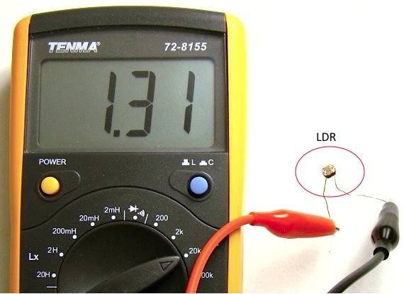
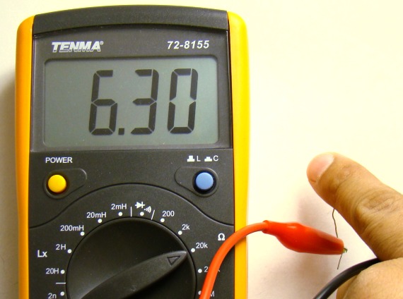
A transducer is an electro-mechanical system that converts physical signals into electrical signals or vice-versa. A simplest example of a transducer is a light dependent resistor or LDR, which can be used to measure the intensity of ambient light. An LDR is a special resistor whose resistance varies with intensity of light falling on its surface. The resistance of an LDR decreases as the light intensity goes up. The pictures below show the measurements of an LDR’s resistance under two different intensities of light falling on it.
An LDR in series with a fixed value resistor can be used to construct a mechanism for converting the light intensity into an electrical voltage. This will be discussed in more detail later. Another example of transducer is an electric motor, which converts an electrical voltage into motion.
Now the physical signal has been converted into an electrical signal but it is not yet ready for computer processing because of its analog nature. The next step, therefore, requires an analog-to-digital conversion (ADC) system that takes a continuously varying voltage input and returns a binary digital representation suitable for use by the microcontroller.
These days many microcontrollers are equipped with analog-to-digital conversion systems. The PIC32MX320F128H microcontoller on the chipKIT UNO32 board has got a built-in ADC with 16 ADC input channels. Out of these only 12 are accessible on Uno32 board through the header pins A0 through A11. The resolution of the ADC is 10-bit, which means 1024 (210) discrete binary representations (0 to 1023) can be made for a given range of an analog signal. The acceptable range of ADC is set through the reference voltage (VREF). The default set reference voltage for the PIC32MX320F128H microcontoller on the chipKIT UNO32 board is its supply voltage (Vcc = 3.3 V). This is also the maximum value of the analog voltage that can be applied to any ADC channel on the chipKIT UNO32 board. Suppose, if the range of the ADC is set to 0-3.3V (VREF=3.3 V), the ADC resolution can also be expressed in terms of voltage as 3.3/1024 ? 3.2 millivolts. This is the smallest change in the analog input voltage that is detectable by the on-chip analog-to-digital (A/D) converter. So, anything between 0 and 3.2 mV will be represented by decimal 0, between 3.2 mV and 6.4 mV by decimal 1, between 6.4 mV and 9.6 mV by decimal 2, …, and finally, between 3.2968 V and 3.3 V by 1023. You can see that with this arrangement, the maximum error in the digital representation of an analog voltage could be 3.2 mV. This is also known as quantization error.
Sometimes the range of the analog input voltage is too small compared to 3.3V and varies only a little bit. For example, the air temperature inside a room does not vary a lot. In such a case you can enhance the resolution of the A/D converter (thus reducing the quantization error) to track the temperature more accurately. Suppose if you know the output voltage from the temperature sensing transducer cannot go beyond 1V, then setting VREF = 1V results in an improved resolution of 1/1024 ? 1 mV. The A/D converter is now capable of detecting much smaller changes in the input signal. An external ADC reference voltage can be supplied to the microcontroller on the chipKIT UNO32 board through its AREF pin, which is labeled as A on connector J5. The maximum voltage that can be applied to this pin is 3.3V.
Circuit setup
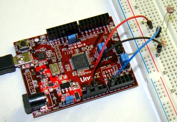
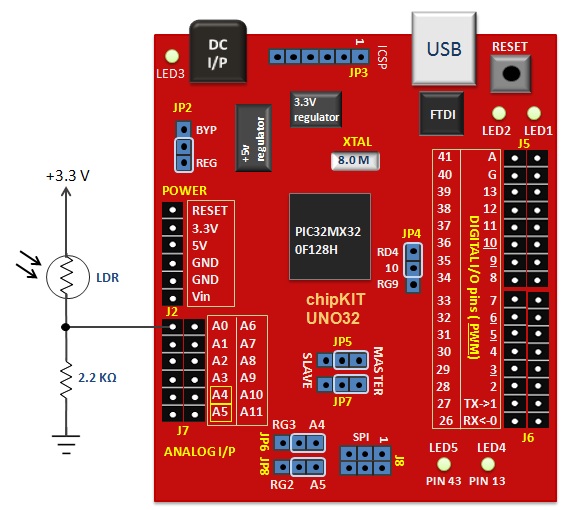
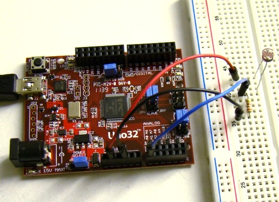
In this tutorial, a 2.2K resistor is connected in series with an LDR to construct a voltage-dividing network, as shown below. The voltage across the resistor is measured through the ADC channel A0 of the Uno32 board. When light falls on the LDR, its resistance decreases, and consequently the voltage across the 2.2K resistor goes up. If the light is blocked from falling onto the LDR, the opposite happens. Therefore, the 10-bit ADC output is proportional to the intensity of light falling on the LDR. The board is connected to the PC and the ADC output will be sent over the serial port and displayed on the serial monitor window.
Writing sketch
Since the ADC outputs are sent over the serial line, the serial port and the baud rate must be initialized in the setup function. The analogRead() function is used to read an analog input signal from the analog pin specified inside the parenthesis. By default, the supply voltage of 3.3V is used as the reference voltage for A/D conversion, which means input voltages between 0 and 3.3 volts are mapped into integer values between 0 and 1023. In order to use an external reference voltage applied to the A pin, use analogReference(External) function in your sketch. Here’s the complete chipKIT sketch to read the input value at A0 ADC channel and print the ADC output to the serial monitor.
/* Tutorial 4: Analog to digital conversion Description: Reads an analog signal input to A0 pin and send the 10-bit ADC output to PC to display on the serial monitor. Board: chipKIT UNO32 */ int ADC_OUTPUT; void setup() { Serial.begin(9600); } void loop() { ADC_OUTPUT = analogRead(A0); Serial.print("LDR sensor output = "); Serial.println(ADC_OUTPUT, DEC); delay(1000); } |
Output
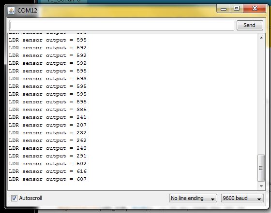
Upload the above sketch into the Uno32 board and open the serial terminal window from MPIDE. The ADC samples (integer ADC outputs) are printed on the window at 1 sec interval. You can watch how these numbers change with the changing intensity of the light falling on the LDR. If you put a finger over the LDR and block the light falling on it, the ADC output will be dropped abruptly.
|
|


is there any way that adc value of 16f688 shown in alphabets (A B O) instead of numeric form
plz help
Thank you so much for theese guides!
they are very helpful!
Gio