chipKIT Project 3: Easy Pulse Meter
|
|
This is a third project in our chipKIT tutorial series and today we are going to construct a simple pulse rate meter using our Easy Pulse sensor with Digilent’s chipKIT Uno32 board. Digilent’s chipKIT Basic I/O shield is also used in this project for displaying the pulse waveform and the pulse rate.
Pulse rate meter using chipKIT Uno32 and Easy Pulse
What do we need?
In order to build this project, we will need following things.
- 1 Easy Pulse sensor
- 1 chipKIT Uno32 board
- 1 chipKIT Basic I/O Shield
- 3 male/female jumper wires (20 cm long)
- Power supply source (9V DC wall adapter or battery with a clip)
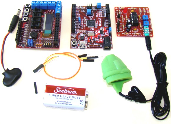
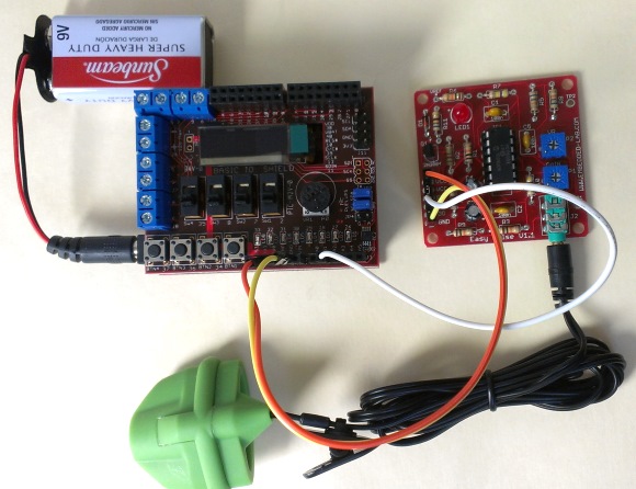
Things required to build this pulse meter
Besides, a USB cable (not shown in the picture above) is also required to upload the firmware from PC to the Uno32 board.
Where to Buy Easy Pulse Sensor?
International customers buy here
Wire Connections and Setup
The OLED display on the Basic I/O Shield is driven through SPI interface. This requires the JP4 jumper on chipKIT Uno32 board be placed on the RG9 position so that the SPI SS function is available on Pin 10. Read our tutorial Exploring the chipKIT Uno32 for more details on jumper functions and settings on the Uno32 board. The following picture shows the required jumper settings on Uno32 board for this project.

Jumper settings on Uno32 board
Now plugin the Basic I/O shield on top of the Uno32 board and connect the Easy Pulse sensor power supply and the analog PPG output pins to the I/O shield as shown in the following figure.
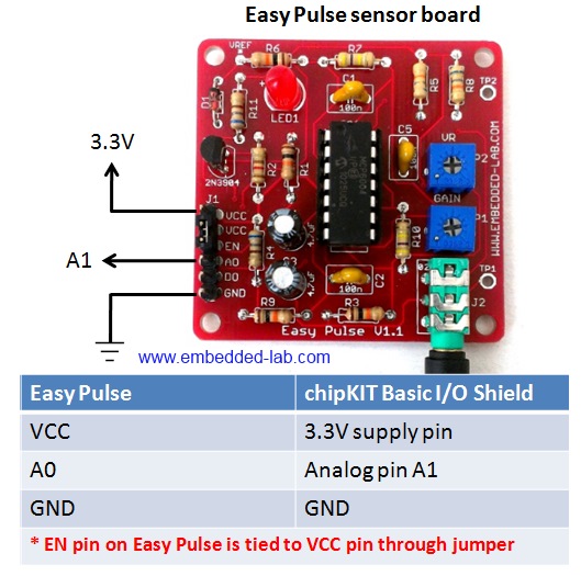
Pin connections between Easy Pulse and I/O shield
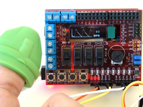
The Easy Pulse board is powered with 3.3V power supply from the I/O board header pins. The analog pulse output from Easy Pulse is connected to analog pin A1 of Uno32 through headers available on the I/O shield. The analog pin A0 of Uno32 may not be used for feeding Easy Pulse output because it is already hard-wired to the potentiometer output on the I/O shield. The following picture shows the complete setup of this project.
Complete project setup
Project sketch
The firmware of this project is based on the same algorithm as used in out previous project PC-based heart rate monitor. The algorithm used by the PC application before is now implemented in the firmware of Uno32. The following flowchart shows the algorithm used to compute the pulse rate. For more detail on this algorithm, visit the PC-based heart rate monitor project.

Algorithm flowchart for computing heart rate
The PPG waveform and the pulse rate (in beats per minute, BPM) are both displayed on the OLED screen of the I/O shield. The Uno32 sketch uses the chipKIT I/O Shield library to display data on the OLED. The complete sketch along with the required library routines is available for download through the following link.
Unzip the downloaded sketch folder and upload the sketch named P3_Uno32_PulseMeter.pde to the Uno32 board.
Demonstration
After the sketch is uploaded, power the Uno32 board through a DC wall adapter or any other external power supply that could be used to power the Uno32 board. Using USB power source is not recommended as some USB ports do not supply enough current for Easy Pulse sensor, in which case the performance of the sensor would be poor. When the sensor is unplugged, the range of ADC would not exceed 50 counts (described in the algorithm) and the pulse meter displays “No Pulse Signal” message on the OLED screen as shown below.
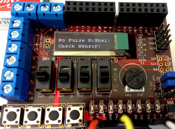
Sensor unplugged
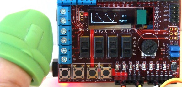
Now wear the Easy Pulse sensor on a finger tip and adjust the P1 potentiometer on the Easy Pulse to 1/4th position from left. The PPG waveform and the pulse rate should now display on the screen. The screen is refreshed in every 3 seconds. If the PPG signal appears clipped at the peak values, consider decreasing the gain of the filter circuit on the Easy Pulse board. This can be done by rotating the P1 potentiometer counterclockwise. Similarly, if you see the “No Pulse Signal” message even after wearing the sensor, you should consider increasing the gain by slightly turning the potentiometer clockwise. Read the Easy Pulse document for more details on the function of P1 and P2 potentiometers of Easy Pulse.
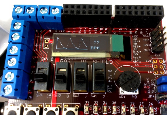
PPG waveform and Pulse Rate displayed on the OLED screen
Here is a demo video that shows the Easy Pulse Meter in action.
|
|
What heart rate measuring range are you able to get with this device? Can it be adjusted to measure a heart rate ~600 bpm?
Thank you,
Sergio
Pingback: BLOG | Stand-alone digital pulse meter using Easy Pulse Plugin and Crowtail modules
Pingback: chipKIT Pulse Meter » chipKIT Development Platform
Pingback: Arduino measures heart beat rate from fingertip - Arduino collector blog
Hi, I work for Digilent Inc and we featured this project on our social media today. Thank you so much for your work this is an excellent post.
Caitlin
Hi Caitlin,
Thank you for sharing it on your social media.
Hi Raj! Can you do a version with a PIC microcontroller?
thank you so much!
Have a good day!
marC:)