XMega Clock System
|
|
Okay firstly the reason I wrote about the clock system instead of I/O ports or something else in this second post of the XMega series is simply because of the fact that without understanding clock configurations you won’t get what you want from your chip. Since XMega’s clock system is software-level configurable and complex at first, it makes itself the first priority module before anything else.
There are several clock sources that XMega micros can use as clock. These are both internal and external clock sources. As stated earlier, clocks are not set by fuse settings unlike traditional Mega AVRs, they are controlled by software and the outputs from these sources can be multiplied using the internal Phase Locked-Loop (PLL). Thus there’s a wide range of clocks available in the XMega and it’ll not be needed to shut down and reprogram the XMega just to change its clock – a great relief from meddling with fuse settings. Some port pins can also output the system clock frequency. Literally there’s no need to depend on external quartz crystals which are not available in all frequencies.
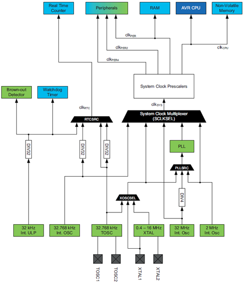
A bird’s eye view of the XMega clock system’s block diagram tells us what we are allowed to use as clock sources and which peripherals run with which clock source(s). It may appear complex but it is actually very easy to understand. If you don’t get it initially don’t worry about it.
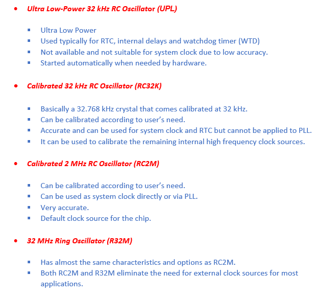
The four internal clock sources apart from external sources that connect to XTAL and TOSC pins and these are:
Any clock source can have more than one use. For example a clock source can provide the clock that drives the CPU and it can also drive another peripheral, e.g. a timer-counter. It is also possible run a number of different clock sources even if none are used as system clock.
There are hardware-level protections that prevent conflicting issues as well as prevent wrong clock selections. To change device clock frequency, the desired clock frequency is set first and then the Configuration Change Protection (CCP) register is configured to disable security for protected I/O register after the source has stabilized because clock-related registers are a part of protected I/O.
Internal or external clock sources can be used as reference sources to the PLL in order to generate higher frequencies. An accurate good quality 32.768 KHz external crystal on TOSC pins or the internal 32.768 kHz oscillator can be used to calibrate the internal 2MHz and 32MHz sources. For calibration purpose the internal Digital Frequency-Locked Loops (DFLL) hardware are used.
External clock sources include typical crystal oscillators/resonators, electronic clock generator circuits, etc. Maximum external crystal frequency is 16MHz but can be increased with PLL. However external clock sources can’t be calibrated since there’s no way an XMega chip has prior knowledge about this source unlike internal clock sources.
If higher frequencies are required, a built-in PLL can be used to multiply a clock source by a factor from 1 to 31. The following clock sources can be used as input to the PLL:
- Internal 2 MHz RC oscillator
- Internal 32 MHz ring oscillator divided internally by 4
- External 0.4 – 16 MHz crystal oscillator
- External clock
Though PLL can multiply a given clock frequency, the user should not exceed the maximum allowed frequency. XMegas can run reliably with a maximum clock frequency of 50 MHz. Check your device’s maximum allowed clock frequency as stated in its datasheet.
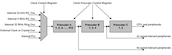
System Clock Selection and Prescalers allow us to generate customized system and peripheral clock frequencies as such that the CPU and other peripherals can run with different clock frequencies.
There are other features in the XMega that are related to clock. One important feature is external clock source failure detector. This module can detect if the external source connected to an XMega controller has failed. It generates an interrupt to notify this failure and the hardware automatically selects the internal 2 MHz clock which is also by the way the default clock whenever the controller resets. In most cases the internal oscillators are accurate enough and external clock sources can be spared. Internal clocks have approximately 1% tolerance.
We will be using the ATXMega32A4U throughout this post. Refer to this document from Atmel for details on XMega clock system: http://www.atmel.com/Images/doc8072.pdf and check the XMEGA AU Manual too. From page 82 to page 102 of the XMega AU Manual, you’ll notice the registers responsible for clock options. I advise reading them at least once.
MikroC compiler has a somewhat different register naming and manipulation strategy for the XMegas and so you’ll find out that whatever written in AVR Studio, Codevision AVR, ImageCraft or other C compiler will certainly not be compatible with it. Due to this different strategy, code examples in the app notes, reference manuals or datasheet are not fully compatible too. Thus I suggest having a glimpse of the ATXMEGA32A4U.c file whenever you write a code for the XMega with MikroC. To access it either go to installation and find in the Defs folder or alternatively press CTRL + ALT + D during coding. You’ll not find this discrepancy Mega/Tiny AVRs. This file will show all the registers and bit field names associated with a chip.
As per Atmel’s documentations, several compilers like the AVR Studio and Codevision AVR have adopted an easy to use bit masking system. Bits of a register in this system can be handled using individual bit masks, group masks, etc. This has tremendously saved coding time. MikroC, on the other hand, doesn’t happen to have facilitated this feature as of version 6.0. This is why AVR Studio code examples will not work with MikroC compiler and this is where MikroC is lagging behind in AVR compiler arena. Though this setback MikroC has other advantages like a lucrative IDE and a well-documented library support. I’m expecting Mikroelektronika to improve AVR compilers.
One of the most useful thing in MikroC compiler is that you can directly access the bits of a register by calling its appropriate bit field name and then adding _bit with it, e.g. XOSCRDY_bit. Thus unlike other compilers there is no need to perform bitwise operations to handle a specific bit. Of course MikroC like other compilers also allow register level accesses too. It’s up to the programmer to decide what he/she prefers. I use a mixture of both.
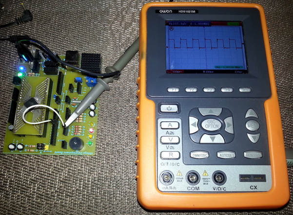
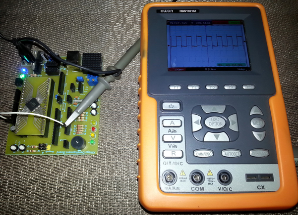
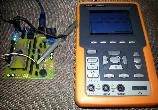
In the code examples I have given with this post, I have followed a systematic order of configuring the clock option. In all of these examples I have used port pins to output system clock frequencies for verification purposes. It’ll be clear in the future why I wrote the code in a specific manner. One more thing you should notice while creating a new project with MikroC is the absence of options to configure fuse settings. I don’t know for sure why it is so but I believe that since the clock options are software-configurable and the rest of the fuses are literally not needed to be touched most often, MikroElektronika just skipped it. Probably they will add this feature in future version of the compiler.
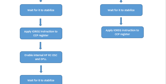
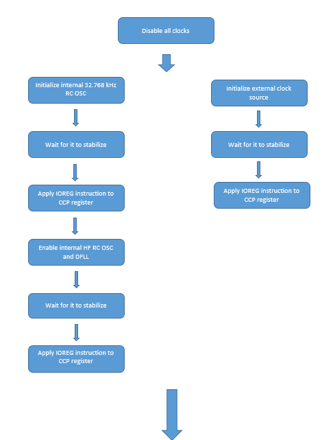
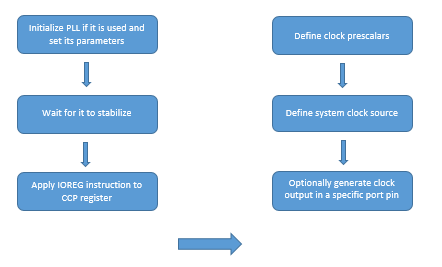
The basic way to configure a clock is firstly to disable all clocks and then turning on the needed clock source. The oscillator control register – OSC_CTRL is first cleared. If internal high frequency (2 MHz and 32 MHz) clocks are used then I strongly suggest calibrating them with DFLLs and the internal 32.768 KHz oscillator. You can also use an external clock crystal connected to TOSC pins for calibration too. Calibration improves timing accuracies. Since the 32.768 kHz internal RC oscillator is also a clock source it is enabled first and the program should wait for it get stabilized. During this time no other task is allowed. After this the CCP register is loaded with IOREG instruction value (0xD8). This temporarily disables protect I/O registers and all interrupts are disabled for 4 clock cycle. It may sound a bit weird but some functions of the XMegas are protected this way. Conceptually it is similar to putting a password to open a safe. Without feeding the CCP with that value no change will be done to the system clock no matter what you code. Thus it is very important to load the CCP register with IOREG instruction every time after a clock’s stabilization flag sets. Unfortunately MikroC named CCP register as CPU_CCP and also didn’t put any definition or macro for the IOREG instruction. As I said earlier you’ll need to check the ATXMEGA32A4U.c file whenever you get stuck with register naming. The same steps as stated above apply to the actual system clock that will be calibrated. There are DFLL registers for both the 2 MHz and 32 MHz RC clock source and these must set accordingly for calibration. For external clock there’s no provision for calibration and so only the external oscillator is enabled and polled till it is stable. Following clock source selection the programmer has also to set prescalers for the peripherals and the CPU. If the PLL is used then it has to be programmed too.
Clock output can be taken from some I/O pins. As I mentioned before, I will use clock output for checking out if I have set the clock correctly. For that purpose I’ll have to choose which pin I use and I’ll have to set it as an output. I’ll not explain how to use the internal 32.768 kHz RC oscillator as clock source because we mostly don’t run micros with such low frequencies. At such low frequencies a micro will operate slowly. However running a micro at low frequencies has low power consumption advantage. The procedure for using the internal 32.768 kHz RC oscillator is similar to the other RC sources. If you have understood how other oscillators work then it won’t be a trouble configuring it. I’ll also not explain I/O ports in this doc but I’ll explain it in the next doc. Just imagine that XMega’s I/O ports have registers for setting I/O pin directions and output registers to switch output states. It’s just for now same as that in a Mega AVR – a data direction register (DDR) and PORT register. We’ll set either PORTC7 bit or PORTD7 bit in the examples as outputs and extract clock out from either of these pins. This will be enough for now. Check out the code examples:
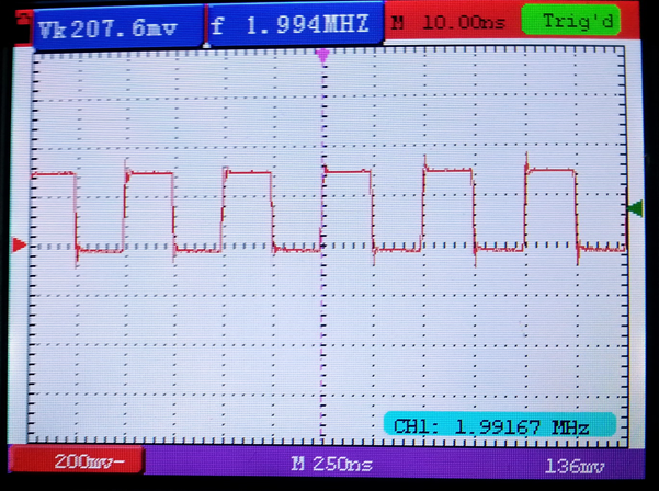
Internal 32MHz RC oscillator without PLL (f out = 2MHz, Prescalar A = 16, B = 1, C = 1, PLL = N/A)
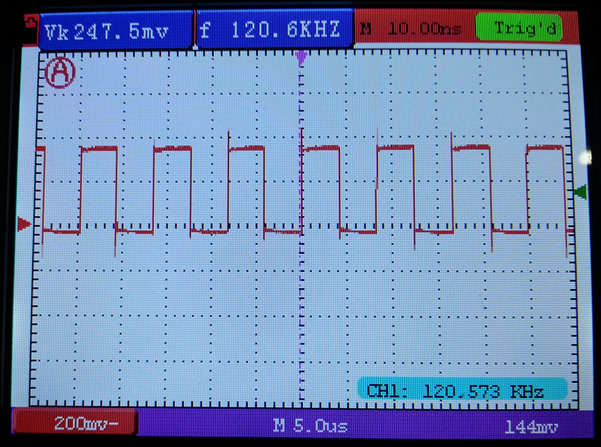
Internal 2MHz RC oscillator with PLL (f out = 121 kHz, Prescalars A = 512, B = 1, C = 1, PLL = 31)
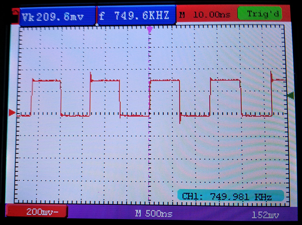
External 12MHz quartz crystal clock (f out = 750 kHz, Prescalars A = 16, B = 1, C = 1, PLL = N/A)
There are a few things that I skipped in this post and I leave them for future. These things are related to USB, clock setting locking mechanism, oscillator fail safe monitor and its interrupt. Other than these the code examples given in this write-up are generic and widely used.
To summarize XMega has a robust clock system that is independent of fuse settings and has several options to play with. Though apparently complicated, the clock system is very easy to configure.
That’s all for now. The next post will be on XMega I/O ports. Till then happy playing with the XMega.
Author: Shawon M. Shahryiar
https://www.facebook.com/groups/microarena/
https://www.facebook.com/MicroArena
|
|
Having read this I thought it was extremely informative.
I appreciate you taking the time and effort
to put this content together. I once again find myself spending a
lot of time both reading and posting comments. But so what,
it was still worth it!
Thanks…. 🙂