Tag Archives: ATXMega32A4U


XMega DAC

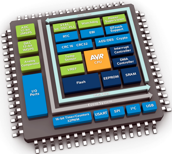
In embedded systems, oftentimes it is needed to generate analog outputs from a microcontroller. Examples of such include, generating audio tones, voice, music, smooth continuous waveforms, function generators, voltage reference generators, etc. Traditionally in such cases the most common techniques applied are based on Pulse Width Modulation (PWM), resistor networks and external Digital-to-Analog Converter (DAC) chips like MCP4921. The aforementioned techniques have different individual limitations and moreover require external hardware interfacing, adding complexities and extra cost to projects.  XMega micros are equipped with 12 bit fast DACs apart from PWM blocks and again it proves itself to be a very versatile family of microcontrollers. In this post we will have a look into this block.

DAC Internal Block Diagram

Read more

XMega External Interrupt

External interrupts are a must have feature in any microcontroller. Interrupts solve a lot of problem that would have otherwise been dependent on polling methods. For instance when we press the volume up key of a TV tuner’s remote controller, the remote controller quickly responds by transmitting the volume up command to the TV set and in turn the TV’s volume increases. This fast response is due to external interrupt issued by the remote’s button to the microcontroller it is connected to. If, however, all the keys of the remote were regularly and frequently scanned and then responded up on a press, the process would have been both slow and energy consuming because its microcontroller would then have never went to sleep or low power states and continuously kept scanning. In other words, the micro would have always ran despite no mandatory necessity and during standby conditions. This would have quickly drained the batteries. Since interrupt is typically used in such cases the remote controller will respond to a button press fast, wake up from sleep/idle/low power mode, transmit command data and then go back to sleep/idle/low power state. Thus the overall energy consumption is reduced while achieving fastest possible reaction. This is how real world applications work applying external interrupts.

XMega 3D


Read more

XMega Analog Comparator

Previously we dealt with the XMega Analog-to-Digital Converter (ADC) block. We know that we can use the ADC to measure voltages and take decisions based on voltage values/levels but sometimes it is enough to detect voltage levels and not to measure the exact voltage values. In such occasions where we just need to check voltage levels relative to a reference or threshold value, we need an Analog Comparator (AC). An analog comparator can be used to compare two voltage levels and based on that it can be used to generate a logic output (0 or 1) to indicate which of the two levels is higher or lower than the other. That’s all and there isn’t much about analog comparators. The XMega family of micros come loaded with high performance dual analog comparator modules. However so far we saw that between the traditional 8-bit micros and the XMega micros, the major difference apart from programming is the overall nifty enhancements in all common hardware blocks. When it comes to the analog comparators of the XMega micros, the same is true. In this issue we will explore the XMega analog comparator block.

Block Diagram


Read more

XMega ADC

For users of advance MCUs like the XMega it is not necessary to tell what an analog-to-digital converter (ADC) is or what it does. I assume this is not the first family of microcontroller they are dealing with. Unlike the ADCs of other microcontroller the ADC of XMega devices is a highly complex tool. The level of complexity is so much that without understanding every bits-and-pieces of this piece of hardware a user won’t enjoy its absolute power. XMega ADC is also the most confusing hardware as it is not like other MCU ADCs. We will be dealing with ATXMega32A4U and it has only one ADC block, named ADCA but some other XMega devices like the XMega128A1 have more than one ADC block – ADCA and ADCB. By the way the XMega reference manual provides a long literature on the ADC and I’m not willing to state everything.

A quick view of the ADC block diagram shows most of the internal arrangement.

ADC internal

Read more

XMega Clock System

Okay firstly the reason I wrote about the clock system instead of I/O ports or something else in this second post of the XMega series is simply because of the fact that without understanding clock configurations you won’t get what you want from your chip. Since XMega’s clock system is software-level configurable and complex at first, it makes itself the first priority module before anything else.

There are several clock sources that XMega micros can use as clock. These are both internal and external clock sources. As stated earlier, clocks are not set by fuse settings unlike traditional Mega AVRs, they are controlled by software and the outputs from these sources can be multiplied using the internal Phase Locked-Loop (PLL). Thus there’s a wide range of clocks available in the XMega and it’ll not be needed to shut down and reprogram the XMega just to change its clock – a great relief from meddling with fuse settings. Some port pins can also output the system clock frequency. Literally there’s no need to depend on external quartz crystals which are not available in all frequencies.

XMega Clock System Internal
Read more

« Older Entries