XMega External Interrupt
|
|
External interrupts are a must have feature in any microcontroller. Interrupts solve a lot of problem that would have otherwise been dependent on polling methods. For instance when we press the volume up key of a TV tuner’s remote controller, the remote controller quickly responds by transmitting the volume up command to the TV set and in turn the TV’s volume increases. This fast response is due to external interrupt issued by the remote’s button to the microcontroller it is connected to. If, however, all the keys of the remote were regularly and frequently scanned and then responded up on a press, the process would have been both slow and energy consuming because its microcontroller would then have never went to sleep or low power states and continuously kept scanning. In other words, the micro would have always ran despite no mandatory necessity and during standby conditions. This would have quickly drained the batteries. Since interrupt is typically used in such cases the remote controller will respond to a button press fast, wake up from sleep/idle/low power mode, transmit command data and then go back to sleep/idle/low power state. Thus the overall energy consumption is reduced while achieving fastest possible reaction. This is how real world applications work applying external interrupts.
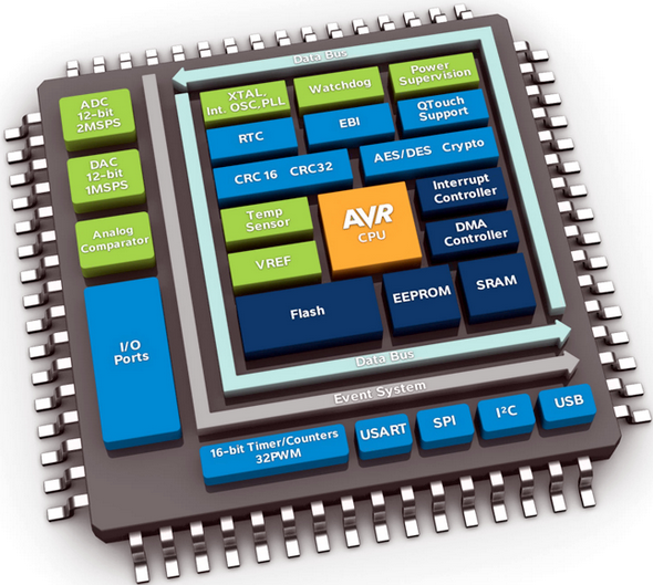
XMega devices just like any micro are equipped with interrupts for both external and internal peripherals but it is more than you can even guess. Any I/O pin or group of I/O pins can be used for external interrupt. Now that’s a cool feature and a great relief as well because most traditional 8-bit micros like the ATMega328P, which is by the way the most widely used by the Arduino community, has only two external interrupts and fixed to one I/O port only. Other larger Mega AVRs have up to eight external interrupts. However XMega’s interrupt system is much more complex than those traditional AVRs. XMega devices support both maskable and non-maskable interrupts (NMI). Currently, however, there is only one NMI and it occurs due to crystal oscillator failure event. NMI is independent of global interrupt enable status. Unlike most traditional micros, interrupt priority can be set apart from edge selection and other stuffs. Priority setting has the effect of determining which interrupt can or will further interrupt another interrupt and so forth.
The PMIC and Interrupt Priority
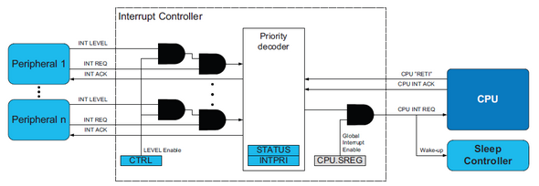
The Programmable Multilevel Interrupt Controller (PMIC) is responsible for handling and prioritizing interrupt requests. As with any microcontroller the global interrupt flag (SREG_I_bit) should be set before using the interrupt system. When a given interrupt condition is enabled and present, the PMIC receives interrupt request and it either acknowledges it or keeps it waiting based on interrupt priority and ongoing interrupts (if any). After executing an interrupt request, the PMIC returns to the proper interrupt level or to a state before the occurrence of the interrupt.
XMega reference manual states that there are three possible interrupt priority levels:
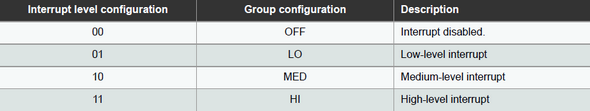
The PMIC prioritizes interrupts according to the following order: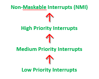
This shows that a higher order interrupt will interrupt a lower order interrupt if both are occurring at the same instance. After processing the higher order interrupt the lower order interrupt is processed. Within a given order, interrupts with lower interrupt vector addresses have higher priorities than those with higher addresses. Typically reset has the highest priority and the lowest interrupt vector address. The same is true for XMega micros too. NMI is the next highest priority interrupt request.
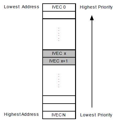
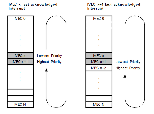
In the XMega, there are two types of interrupt and these are static and dynamic. Static interrupts are those which have fixed vector addresses while low priority interrupts are dynamic and this dynamic behaviour is achieved by Round-robin Scheduling (RRS) technique. The RRS ensures that the low level interrupts are not skipped. If this technique is applied then the last invoked interrupt will have the lowest priority for one or more interrupts. Thus within the low level interrupt there is a mechanism that makes sure that all of them are served within a certain time frame.
Interrupt Service Routine in XMega Devices
All maskable interrupt peripherals have interrupt flags and settings to set interrupt priority as well as enabling them. Irrespective of its settings an interrupt flag will be set when it occurs. The interrupt flags in most cases are automatically cleared up on executing them or by setting them in software.
Some key points regarding interrupt handling:
- When a higher priority interrupt is ongoing and lower priority interrupt invokes, the lower priority interrupt is remembered and kept pending until its priority comes.
- When a higher priority interrupt overtakes an ongoing lower priority interrupt, the lower priority interrupt is remembered and served after executing the higher priority interrupt.
- If an interrupt has lower vector address then it will overtake another interrupt of same priority having a higher address. The latter will be remembered and served after executing the former.
- If an interrupt is disabled and it occurs, it is remembered until it is enabled or cleared by software. Previously in my post regarding the XMega ADC block we encountered this stuff.
- If interrupts occur when the global interrupt enable bit is disabled, all of the interrupts are remembered and processed according to priority when the global interrupt is enabled.
- Active interrupts can be cleared by issuing clear interrupt instruction asm cli; in assembly. This is just the opposite of global interrupt enable using the asm sei; instruction.
Remember these points when watching the code example video. You’ll certainly see all these happen.
Interrupt Disarmament
All maskable interrupts are disabled for four clock cycles automatically when the Configuration Change Protection (CPU_CCP) register is feed with two correct instruction signatures. These are:
- Protect I/O instruction (CCP_IOREG, 0xD8).
Prevents unintentional writes into protected peripheral registers. We already encountered it in the XMega Clock System post. - Store Program Memory (CPU_SPM, 0x9D).
Used to write to the XMega’s flash memory from application software.
Correct signature values as above should be feed to the CPU_CCP register before executing SPM instruction or modifying protected peripheral registers.
XMega Port Interrupt
Before understanding I/O port pin interrupt, I would like to request readers to brush up my earlier post on XMega I/O Ports here because in that post I discussed about edge selection as well as other I/O port pin properties which are necessary for external interrupts. The I/O pins of the XMega are such that an external interrupt can occur when the logic state of a single pin or a group of pins changes. Every port in an XMega device has two independent external interrupt vector addresses (INT0 and INT1).
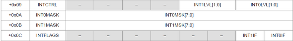
To configure external interrupts, we need to configure I/O pins first. After having I/Os setup, interrupt priorities are set for respective vector address. Finally before setting global interrupt flag, interrupt pin masks are applied to set which pins will invoke a given interrupt. When an interrupt occurs its corresponding flag is set. Shown below are port pin interrupt registers. We’ll have to set them.
Coding
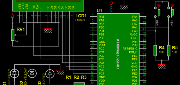
The example code for external interrupt not only demonstrates the typical external interrupt response but also shows how priorities are handled. The ATXMega32A4U I used in this post runs at 8MHz clock derived from prescaled internal 32MHz oscillator. There are three LEDs (Red, Yellow and Green), two push buttons and a 16×1 LCD attached to the XMega micro as shown:
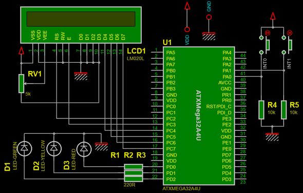
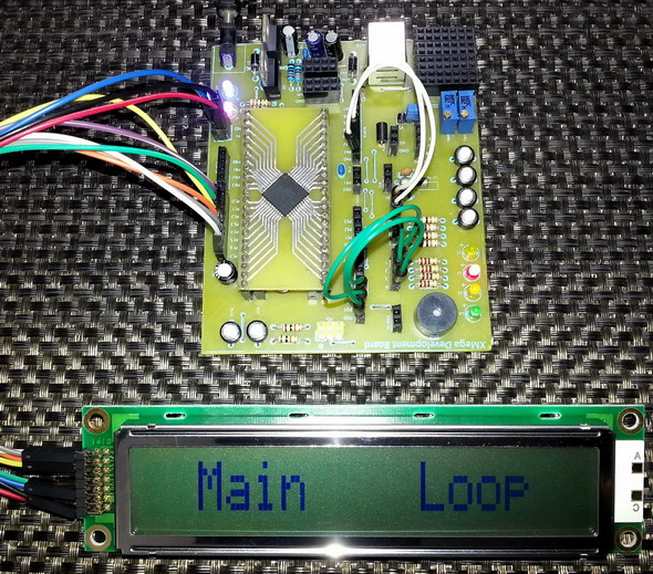
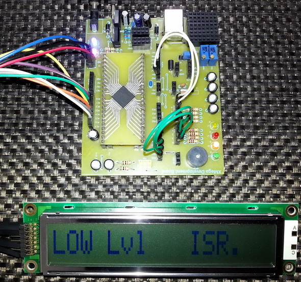
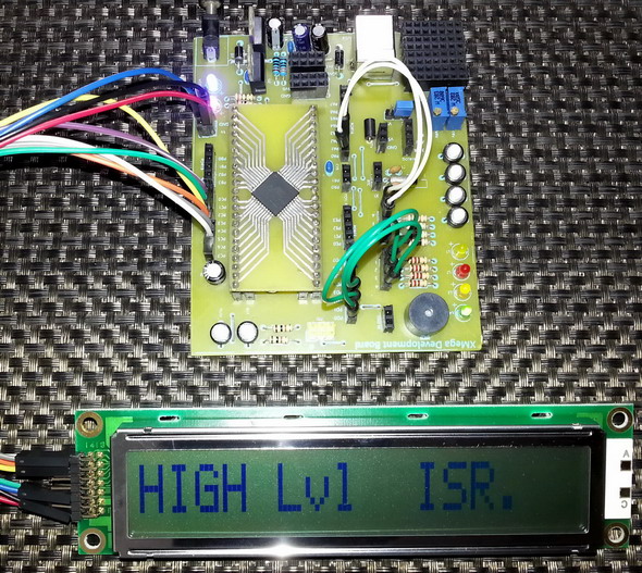
I/O pin PA0 is programmed as INT0 pin while PA1 is programmed as INT1 pin. Both pins are configured to sense rising edge. Without any interrupt the main loop executes and the LCD shows “Main Loop” and D3 (Red LED) blinks. When INT0 (low level) interrupt occurs due to button press, the LCD shows “LOW Lvl ISR.” and D2 (Yellow LED) blinks sixteen times, halting the actions of the red LED. Similarly when INT1 (high level) interrupt occurs the LCD shows “HIGH Lvl ISR.” and D1 (Green LED) blinks sixteen times, pausing the actions of other two LEDs. After executing an interrupt either the next priority interrupt is served or moved to the main loop. In the example you’ll notice everything I mentioned about Interrupt Service Routine (ISR) execution here.
#include "io.h"
#include "clock.h"
#include "interrupt.h"
sbit LCD_RS at PORTC_OUT.B2;
sbit LCD_EN at PORTC_OUT.B3;
sbit LCD_D4 at PORTC_OUT.B4;
sbit LCD_D5 at PORTC_OUT.B5;
sbit LCD_D6 at PORTC_OUT.B6;
sbit LCD_D7 at PORTC_OUT.B7;
sbit LCD_RS_Direction at PORTC_DIR.B2;
sbit LCD_EN_Direction at PORTC_DIR.B3;
sbit LCD_D4_Direction at PORTC_DIR.B4;
sbit LCD_D5_Direction at PORTC_DIR.B5;
sbit LCD_D6_Direction at PORTC_DIR.B6;
sbit LCD_D7_Direction at PORTC_DIR.B7;
void setup_clock();
void setup_io();
void setup_interrupts();
void setup_lcd();
void PORTA_INT0_ISR()
org IVT_ADDR_PORTA_INT0
{
unsigned char s = 16;
while(s > 0)
{
Lcd_Cmd(_LCD_CLEAR);
Lcd_Out(1, 1, "LOW Lvl");
Lcd_Out(2, 3, "ISR.");
PORTD_OUT.B1 ^= 1;
delay_ms(200);
s--;
}
}
void PORTA_INT1_ISR()
org IVT_ADDR_PORTA_INT1
{
unsigned char s = 16;
while(s > 0)
{
Lcd_Cmd(_LCD_CLEAR);
Lcd_Out(1, 1, "HIGH Lvl");
Lcd_Out(2, 3, "ISR.");
PORTD_OUT.B2 ^= 1;
delay_ms(200);
s--;
}
}
void main()
{
setup_interrupts();
setup_clock();
setup_io();
setup_lcd();
while(1)
{
Lcd_Cmd(_LCD_CLEAR);
Lcd_Out(1, 3, "Main");
Lcd_Out(2, 3, "Loop");
PORTD_OUT.B0 ^= 1;
delay_ms(900);
}
}
void setup_clock()
{
clear_global_interrupt();
OSC_CTRL |= OSC_RC32KEN_bm;
while(!(OSC_STATUS & OSC_RC32KRDY_bm));
DFLLRC32M_CTRL = 0;
OSC_CTRL |= OSC_RC32MEN_bm;
while(!(OSC_STATUS & OSC_RC32MRDY_bm));
OSC_DFLLCTRL = OSC_RC32MCREF_RC32K_gc;
DFLLRC32M_CTRL = DFLL_ENABLE_bm;
CPU_CCP = CCP_IOREG_gc;
CLK_PSCTRL = (CLK_PSADIV_4_gc | CLK_PSBCDIV_1_1_gc);
CPU_CCP = CCP_IOREG_gc;
CLK_CTRL = CLK_SCLKSEL_RC32M_gc;
OSC_CTRL &= ~(OSC_RC2MEN_bm | OSC_XOSCEN_bm | OSC_PLLEN_bm);
PORTCFG_CLKEVOUT = 0x00;
}
void setup_io()
{
PORTA_OUT = 0x00;
PORTA_DIR = 0x00;
PORTA_PIN0CTRL = (PORT_OPC_TOTEM_gc | PORT_ISC_RISING_gc);
PORTA_PIN1CTRL = (PORT_OPC_TOTEM_gc | PORT_ISC_RISING_gc);
PORTA_PIN2CTRL = (PORT_OPC_TOTEM_gc | PORT_ISC_BOTHEDGES_gc);
PORTA_PIN3CTRL = (PORT_OPC_TOTEM_gc | PORT_ISC_BOTHEDGES_gc);
PORTA_PIN4CTRL = (PORT_OPC_TOTEM_gc | PORT_ISC_BOTHEDGES_gc);
PORTA_PIN5CTRL = (PORT_OPC_TOTEM_gc | PORT_ISC_BOTHEDGES_gc);
PORTA_PIN6CTRL = (PORT_OPC_TOTEM_gc | PORT_ISC_BOTHEDGES_gc);
PORTA_PIN7CTRL = (PORT_OPC_TOTEM_gc | PORT_ISC_BOTHEDGES_gc);
PORTA_INTCTRL = (PORT_INT1LVL_HI_gc | PORT_INT0LVL_LO_gc);
PORTA_INT0MASK = 0x01;
PORTA_INT1MASK = 0x02;
PORTD_OUT = 0x00;
PORTD_DIR = 0x07;
PORTD_PIN0CTRL = (PORT_OPC_TOTEM_gc | PORT_ISC_BOTHEDGES_gc);
PORTD_PIN1CTRL = (PORT_OPC_TOTEM_gc | PORT_ISC_BOTHEDGES_gc);
PORTD_PIN2CTRL = (PORT_OPC_TOTEM_gc | PORT_ISC_BOTHEDGES_gc);
PORTD_PIN3CTRL = (PORT_OPC_TOTEM_gc | PORT_ISC_BOTHEDGES_gc);
PORTD_PIN4CTRL = (PORT_OPC_TOTEM_gc | PORT_ISC_BOTHEDGES_gc);
PORTD_PIN5CTRL = (PORT_OPC_TOTEM_gc | PORT_ISC_BOTHEDGES_gc);
PORTD_PIN6CTRL = (PORT_OPC_TOTEM_gc | PORT_ISC_BOTHEDGES_gc);
PORTD_PIN7CTRL = (PORT_OPC_TOTEM_gc | PORT_ISC_BOTHEDGES_gc);
PORTD_INTCTRL = (PORT_INT1LVL_OFF_gc | PORT_INT0LVL_OFF_gc);
PORTD_INT0MASK = 0x00;
PORTD_INT1MASK = 0x00;
set_global_interrupt();
}
void setup_interrupts()
{
clear_global_interrupt();
CPU_CCP = CCP_IOREG_gc;
PMIC_CTRL = (PMIC_LOLVLEN_bm | PMIC_HILVLEN_bm);
PMIC_INTPRI = 0x00;
}
void setup_lcd()
{
Lcd_Init();
Lcd_Cmd(_LCD_CLEAR);
Lcd_Cmd(_LCD_CURSOR_OFF);
}
Demo video link: https://www.youtube.com/watch?v=N5UjBS_hjlg.
So far we just dealt with external interrupts but there are also interrupts that result due to internal hardware peripherals like timers, communication modules, ADC, etc. I’ll discuss about them in my upcoming posts when I deal with those hardware. Should you have understood how external interrupts work in the XMega, I believe you have clearly understood how other interrupts will behave. Lastly please do read the reference manual for more clear understanding.
Files: XMega External Interrupt.
References:
- XMega AU Manual and Datasheet.
- Atmel’s Official Website https://www.atmel.com
Happy coding.
Author: Shawon M. Shahryiar https://www.facebook.com/groups/microarena https://www.facebook.com/MicroArena +8801970046495 06.02.2015|
|
Thanks for this tutorial – it was somewhat better than wading through ASF’s “I am very clever and I’ll show you how clever by obfuscating a simple task with structures, and myriads of include files”.
OK, I appreciate they’re going for flexibility, but I’m sorry, I don’t want my interrupts flexible. They are as flexible as an etched copper track – I don’t want to include them in a structure, because they ain’t gonna move!
However, I said ‘somewhat.
Bit disappointed by the lack of comments – I understand the overworked “The Code is the documentation”, but I am still at a loss to understand why all unused pins in your code are set up to be (PORT_OPC_TOTEM_gc | PORT_ISC_BOTHEDGES_gc);
Is this something I need to be aware of?
Why suddenly revert ot “Magic Numbers” – PORTA_INT0MASK = 0x01; instead of PORTA_INT0MASK = PIN0_bm; ?
But, otherwise, after puzzling through it (and realising it’s for MikroC, not AVR) I think I’m getting it.
Think I need to flowchart it for myself. It is difficult, going from Mega to Xmega – so many things to remember!
Many thanks, and look forward to more XMEGA stuff. I love the part, just takes longer to learn than I thought!
-Andy
It is not mandatory to set unused I/O pins as (PORT_OPC_TOTEM_gc | PORT_ISC_BOTHEDGES_gc);. Please check that I didn’t use I/O pins of other ports and I didn’t declare anything for them. However it is a good practice to keep unused pins in their default states as I did with that piece of code. Of course the code is the documentation should you understand each line. I don’t have a habit of writing comments and I’m sorry about it.
Regarding “PORTA_INT0MASK = 0×01; instead of PORTA_INT0MASK = PIN0_bm;”, I will say both are compatible statements but in my headers I didn’t declare anything like PIN0_bm and so I used hexadecimal numbers instead. I noted this part and will get it updated. There’s always a room for improvement. Thanks for the suggestion.
Indeed XMegas are different from old school Mega AVRs. This makes them difficult to use without remembering so many stuffs.
Thanks…. 🙂