chipKIT Tutorial 1: Digital input and output

|
|
Our first chipKIT tutorial is about reading and writing digital data (0 or 1) from and to an I/O pin of the chipKIT board. Digital inputs are useful to determine whether an incoming digital signal is logic HIGH or logic LOW. A simple application of digital input is reading the state of a push-button switch and perform some action based on if the switch has been pressed or not. Similarly, digital outputs are used by microcontrollers for many purposes, such as to enable or disable an external chip, drive LEDs and LCD displays, control relay switches, etc. In this tutorial, we will build a very simple circuit using a momentary push-button and an LED, both connected to the digital I/O pins of chipKIT Uno32. The state of the switch is continuously read by Uno32, which then toggles the LED on and off every time the switch is pressed.
Circuit setup
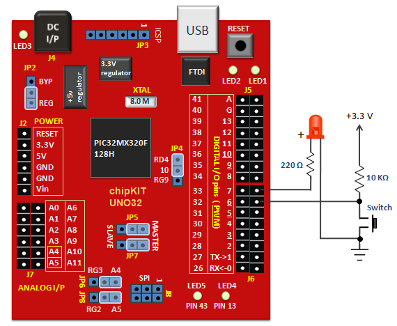
Shown below is the circuit diagram showing the required setup for this tutorial. An external LED is connected to I/O Pin 7 through a 220? series resistor. The resistor is required to limit the current passing through the LED to a safe value. The LED turns on when Pin 7 is set HIGH. It should be noted that the chipKIT I/O pins can source or sink a maximum of 18mA on all digital I/O pins. The potential drop across a red LED is usually around 1.9-2.1V. When a chipKIT Uno32 I/O pin is set HIGH, the output voltage is 3.3V. Therefore, the current sourced by Pin 7 while driving the LED on is (3.3-1.9)/220 ? 6mA, which is well within the safe limit.
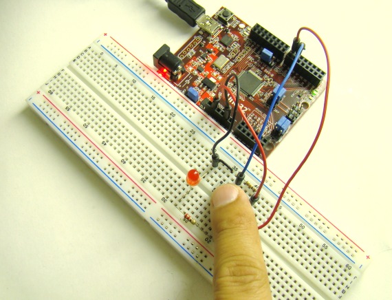
Next, a momentary push button switch is connected to Pin 6. The switch remains closed as long as it is pressed, and is open when it is released. The 10K resistor connected in series with the switch is called pull-up resistor, because it pulls one of the switch terminals to logic HIGH (3.3V) under default condition. So when the switch is in the released condition, the digital input from the switch will be logic HIGH. When the switch is pressed, the digital input is connected to ground, which will be read as logic LOW. The picture below shows the circuit setup on a breadboard.
Writing sketch
The following program continuously reads the state of the push-button and toggles the LED each time the switch press is detected. Each digital I/O pin on the chipKIT UNO32 board can be configured as an INPUT or OUTPUT by using the pinMode instruction as discussed in the previous tutorial (Getting acquainted with the chipKIT programming tool). So, Pin 6 is defined as digital input and Pin 7 as digital output.
/* Tutorial 2: Digital Input and Output Description: A tact switch is connected to digital I/O pin 6 and an LED to pin 7. The LED will toggle ON and OFF when the switch is pressed. Board: chipKIT UNO32 */ // Set pin numbers using constants const int SWITCH_PIN = 6; // Pin number of the push button const int LED_PIN = 7; // Pin number of the LED // Variable SWITCH_STATE stores the logic state of the Push Switch pin // and LED_STATE stores the current state of LED, which is initially OFF. int SWITCH_STATE = 0, LED_STATE = 0; void setup() { // Initialize the push switch pin as inputLED pin as an output: pinMode(SWITCH_PIN, INPUT); // And the LED pin as an output pinMode(LED_PIN, OUTPUT); //digitalWrite(LED_PIN, LOW); } void loop(){ // Read the state of the switch SWITCH_STATE = digitalRead(SWITCH_PIN); // Check if the switch is pressed. It returns logic low when pressed. if (SWITCH_STATE == LOW) { if(LED_STATE == 0){ digitalWrite(LED_PIN, HIGH); LED_STATE = 1; } else { digitalWrite(LED_PIN, LOW); LED_STATE = 0; } // Wait for 300ms before reading the switch state again delay(300); } } |
The digitalRead function monitors the voltage on the specified input pin, and it returns High if the input is high (+3.3V), and returns Low if the input is Low. Note that the switch returns logic Low when pressed. A 300 milliseconds delay is implemented in between two successive readings of the switch state so that if the switch is being actively pressed for 300 ms, it will be read as only a single press.
Output
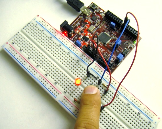
Download the above sketch into the chipKIT Uno32 board using the Upload button in the toolbar. Initially, the LED is turned off. When the switch is pressed the first time, the LED turns on. On the second press, it will turn off. The LED turns on again on the third press, and so on. If the switch is actively being pressed, the LED toggles on and off in every 300 ms.
Go to the main tutorial page : chipKIT Programming and Interfacing
|
|


Your image is broken, can you please fix this!
Does the chipKit support internal pull ups? Or did you use an external to explain the concept?
An external 10K pull-up resistor was used to illustrate the concept. Internal pull ups in Uno32 might not work exactly the same as in Arduino.