Add a thermometer to your digital multimeter
|
|
A digital multimeter is a very useful instrument that combines several measurement functions in one unit. A typical multimeter includes features of a variable-range ohmmeter, voltmeter, and ammeter. Some of them also include capabilities of testing diodes and transistors. In this article, I am going to talk about a technique of adding thermometer feature to a regular digital multimeter. The technique is very simple and uses one temperature sensor along with two resistors and a DPDT slide switch.

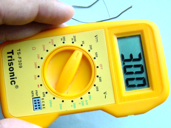
Multimeter showing the surrounding temperature in degree Celsius
Theory
In my previous article (Testing analog temperature sensors with a multimeter), I described a method of using a multimeter to test analog temperature sensors like LM34, LM35, MCP9701, TMP35, etc. These sensors provide an analog output voltage that is linearly proportional to the temperature, and therefore, by measuring the output voltage with a multimeter, we can verify if the sensor is working or not. Now we are going to embed one such sensor inside a digital multimeter and use the voltmeter feature of the meter to display temperature on the LCD. The sensor will acquire power supply from the multimeter circuit itself. Although this sounds pretty simple, there are few issues that must be taken care of to make it work.
Let’s look at the setup shown in the picture below. Here, the LM35 sensor is powered from an external 9V battery source and its output is measured with a digital multimeter setup as a voltmeter. The LM35 output is linearly proportional to the Celsius temperature with a scaling factor of +10mV/°C, which means if the temperature is 24.5°C, the multimeter will measure the sensor output as 245 mV. Now the question is will the multimeter output be the same if the LM35 sensor is placed inside the multimeter and powered from the same battery (usually 9V or 12V) that is powering the multimeter? Actually,it is not. Let’s see why.

LM35 output voltage is proportional to centigrade temperature
Most of the inexpensive digital multimeters available in the market are based on ICL7106 chip, which is a low power A/D converter with a built-in 3 1/2 digit LCD display driver. The maximum voltage that can be applied between its power supply pins, V+ and V-, is +15V. However, the multimeters based on this chip are usually seen to be powered by either a 9V PP3 or a 12V A23 battery. Now if the LM35 sensor uses the same battery to power itself, then it will use the negative terminal of the battery as the reference point (ground) to generate the output voltage, which is proportional to the temperature. But the ICL7106 A/D converter does not measure the input voltage with reference to the negative terminal of the battery. Instead, it uses a separate reference voltage (known as common terminal, or COM point) which is derived from the supply voltage and is set somewhere between V+ and V-. The multimeter has two leads: red and black. The black lead goes to the COM terminal (which is the reference point) and the red lead goes to the IN+ terminal of the multimeter circuit. The voltage at IN+ is appropriately scaled (based on the selected range) through an on-board circuit before it is fed to the input of the ICL7106 A/D converter, which then measure it with reference to the COM voltage. The easiest way to find out the voltage of the COM terminal is to set the multimeter as voltmeter and connect the IN+ terminal (red lead) to the positive terminal of the battery as shown below.
 e
e COM and IN+ terminals inside the multimeter
The multimeter will show this voltage around 3V, which means the COM terminal is set to 3V lower than the battery’s positive voltage. I have tested this with a few other digital multimeters and they all show that the COM terminal is 3V lower than the battery’s positive terminal.

Potential difference between the positive terminal of the battery and the COM terminal is 3.0 V
Imagine what would happen if you connect the ground pin of the temperature sensor to the COM lead, instead of the negative terminal of the battery. The sensor will now provide output with reference to the COM terminal and the multimeter will be able to measure the sensor output correctly. But, unfortunately, the LM35 sensor does not operate at 3V. The recommended supply voltage range for LM35 is 4-30 V. But there are other similar sensors that operate at 3V, such as TMP35, which is functionally compatible with the LM35 sensor and operates at a single-supply voltage from 2.7 V to 5.5 V. It also does not require any external calibration to provide typical accuracies of ±1°C at +25°C and has an output scale factor of 10 mV/°C. However, the TMP35 reads temperature only from 10°C to 125°C.
Now we have resolved the reference voltage problem, and found a temperature sensor that operates at 3V. The next thing required is a divide-by-ten circuit. There is a factor of 10 in the sensor’s output voltage (mV) which must be taken out to get the actual temperature (°C). The divide-by-ten circuit can be simply constructed using two resistors (1.8K and 200?) connected in series as a voltage divider. The voltage across the 200? resistor is 1/1o th of the total voltage applied across the series combination of the two. The complete circuit diagram of this setup is shown below. A DPDT slide switch is included in the circuit to turn the thermometer on and off. When the switch is turned on, two things happen:
1. The TMP35 gets power supply.
2. The divided sensor output is connected to the IN+ terminal of the battery.
If you set the multimeter to measure voltage ranging from 0-200 mV, the temperature in °C will be displayed on the LCD screen.

Circuit diagram
In the circuit above, when the switch is turned off, the sensor’s power supply is cutoff, which is important because we don’t want the sensor to draw current from the battery all the time, and the multimeter’s IN+ terminal is disconnected from the sensor so that the multimeter can resume its normal operation.
Here’s my TMP35 sensor with the divide-by-ten network. I didn’t have a 200? resistor so I cascaded two 100? resistors.

Sensor and the resistive voltage divider network

Circuit placed inside the multimeter
I fixed the slide switch next to the battery compartment as shown below.

DPDT slide switch
After the circuit is placed inside the multimeter, put its cover back. Turn the multimeter knob to measure DC voltage between 0-200 mV, and push the slide switch to ON position. The sensor gets powered and its output is connected to the IN+ terminal of the multimeter. The meter then displays the temperature (°C) on the LCD screen.

Displaying room temperature in ° C
The following picture shows the temperature when the meter is placed inside refrigerator. It would probably go further down but I took it out after a couple minutes as the TMP35 can read temperature only above 10°C.

Meter placed inside the refrigerator
Now my multimeter has an added feature of displaying the ambient temperature on its LCD. How about yours?
I hope you enjoyed reading this!
|
|
Hi,
Thanks for amazing circuit and explanation.
Enjoy yourself
Thanks for everything,
But it didn’t work with me, i connect all like the picture with LM35 but I don’t have anything.
please can anybody help me.
Thanks for advance.
Hi.
Can anyone tell me if this works the same with 12v hooked up to a screen that is just a voltmeter?
I want to use one of these dual volt meters to display the temprature of my camping fridge in my 4wd, (the temp sensor can just be on a cable that i shut in the fridge and resisters behind the meter where i mount it)
Thanks,
Mile
Hello!
I just did a small post on my blog based on this project, I hope that you do not mind.
-Cheers.
That’s alright!
Pingback: Multimeter Temperature Mod « Mint Electronics
Pingback: Add a Thermometer to Your Multimeter | Indoor Digital Billboards
Pingback: Add a Thermometer to Your Multimeter
Pingback: Add a Thermometer to Your Multimeter | House of Mods
Pingback: MAKE | Add a Thermometer to your Multimeter
My meter shows ambient temperature out of the box…but then it’s a _real_ multimeter.
Nice. Good article
Pingback: Upgrading a digital multimeter to tell the temperature « Hackaday « Cool Internet Projects
Pingback: Upgrading a digital multimeter to tell the temperature » Geko Geek
Pingback: Upgrading a digital multimeter to tell the temperature | Share Blog
Pingback: Upgrading a digital multimeter to tell the temperature - Hack a Day
Very smart! Nice idea and well done!
I wanted to make a thermometer and a battery monitoring device for my motorbike, now I got the idea that with a cheap multimeter and a few additional components I could make it!
A small PIC10F could simply switch the voltage range and the sensor every 1 sec or so…
I’ll think a bit more about that.