chipKIT Tutorial 7: Using Nokia 5110 LCD
|
|
In Tutorial 4, we learnt interfacing an HD44780-based LCD to a chipKIT board for displaying alphanumeric output. Today, we will see how to connect a NOKIA 5110 graphical LCD (used in Nokia 5110 cell phones), which is a 84×48 pixel monochrome display of about 1.5″ diagonal in size. The display can be used for graphics, text, and bitmaps.
Theory
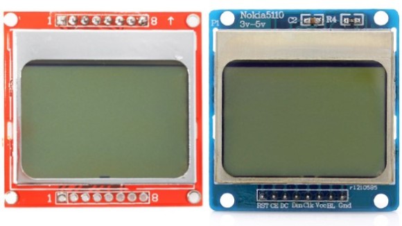
Nokia 5110 LCD was used in Nokia’s popular 5110 and 3310 model cell phones. It is a 48×84 pixels matrix LCD driven by the low-power PCD8544 controller chip. It is powered by 3.3V and includes on-chip generation of LCD supply and bias voltages, thus requiring minimum external components for its operation. The PCD8544 receives display data and commands from a microcontroller through a serial bus interface. There are multiple Nokia 5110 LCD modules in the market; they all come pre-mounted on a PCB and look similar but the pin arrangements might be different in some modules. This is a very popular display among the Arduino community because of its low cost (~$3 on eBay) and simplicity to use with easily available open-source libraries. The LCD requires 5 I/O pins for full control. The pins available in almost every Nokia 5110 LCD modules are listed below:
- RST: Display reset input
- CE: Chip enable input
- DC: Data or Command select signal
- DIN: Serial data input
- CLK: Clock input
- VCC: 3.3V power supply
- BL: Backlight LED anode (connect to 3.3V)
- GND: Power supply ground
Circuit Setup
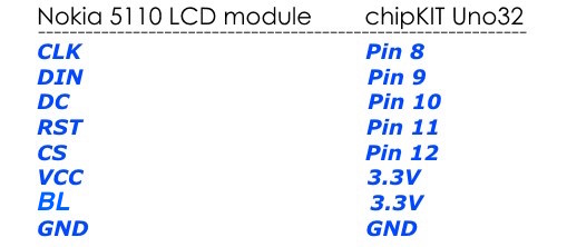
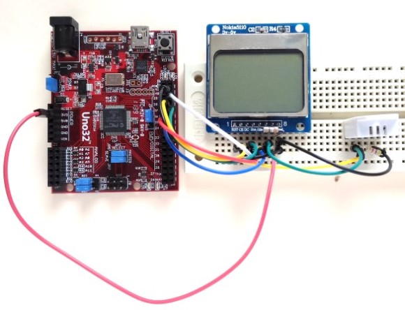
For this experiment, we are using chipKIT Uno32 pins 8 through 12 to drive the data and signal lines of the Nokia 5110 LCD module. The connections are made as follows:
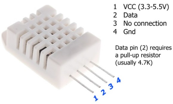
We will also connect a DHT22 temperature and humidity sensor to the chipKIT Uno32 to add more fun to our experiment. DHT22 is a low-cost temperature and humidity sensor that provides calibrated digital outputs through a single wire digital interface. The following figure shows the pin diagrams of the DHT22 sensor.
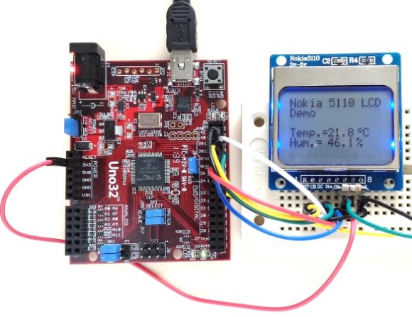
A pull-up resistor (usually 4.7K) must be connected between the Data and VCC pins. In our experiment, the sensor data pin is connected to pin 7 of chipKIT Uno32, while the sensor is powered through the 3.3V supply pin on the chipKIT Uno32 board. The complete setup of this experiment is shown below.
Writing sketch
We will need to install two libraries for developing the firmware for this experiment. The first library required is the standard Arduino DHT22 library, which is modified by Trevor van der Linden to make it work with chipKIT platform. The second one is Nokia 5110 LCD library for chipKIT from Rinky-Dink Electronics. There are two versions of the LCD libraries: LCD5110_Basic, which supports texts, and LCD5110_Graph, which supports text, graph, and bitmaps. Download and install these libraries to your mpide/libraries/ folder using the following download links.
The chipKIT program for this experiment can be downloaded from the following link:
Output
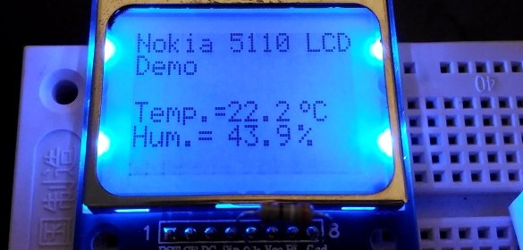
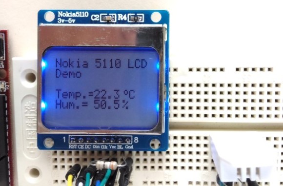
After uploading the chipKIT firmware, the temperature and humidity measurements are displayed on the LCD screen as shown below. The values are refreshed every 5 seconds.
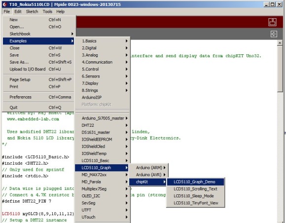
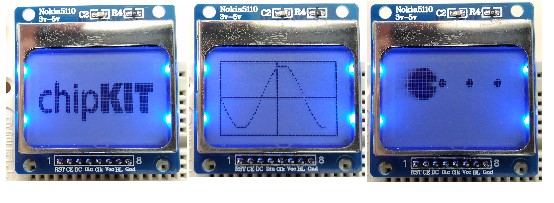
The LCD5110_Graph library comes with some examples of graphical and bitmap displays, which can be found inside the examples sub-folder and accessed easily through MPIDE environment from File->Examples navigation menu as shown below:
I would highly recommend to test and run these examples to get more familiar with the LCD5110 libraries. Simply upload these examples one by one to the Uno32 board without making any changes to the current circuit setup and see the action on the LCD screen.
|
|
Pingback: chipKIT Tutorial: Using Nokia 5110 LCD | Electronics Infoline
Pingback: chipKIT Tutorial: Using Nokia 5110 LCD - Electronics-Lab