Easy Pulse Sensor (Version 1.1) Overview (Part 1)
|
|
The Easy Pulse sensor is designed for hobby and educational applications to illustrate the principle of photoplethysmography (PPG) as a non-invasive optical technique for detecting cardio-vascular pulse wave from a fingertip. It uses an infrared light source to illuminate the finger on one side, and a photodetector placed on the other side measures the small variations in the transmitted light intensity. The variations in the photodetector signal are related to changes in blood volume inside the tissue. The signal is filtered and amplified to obtain a nice and clean PPG waveform, which is synchronous with the heart beat. The original version of Easy Pulse uses the TCRT1000 reflective optical sensor to sense the blood variation in the finger tissue and outputs a digital pulse which is synchronous with the heart beat. Today, we are pleased to announce the release of Easy Pulse Version 1.1, which has some improvements over the original design. The new version provides both analog PPG waveform as well as digital pulse signal as separate outputs. Easy Pulse Version 1.1 board is available for purchase on Tindie. Recently, our Chinese distributor Elecrow has also started selling it for $18.50, and they can ship it world-wide at lower cost.

Easy Pulse version 1.1
Quick overview of Easy Pulse
The Easy Pulse sensor is based on the principle of photoplethysmography (PPG) which is a non-invasive method of measuring the variation in blood volume in tissues using a light source and a detector. Since the change in blood volume is synchronous to the heart beat, this technique can be used to calculate the heart rate. Transmittance and reflectance are two basic types of photoplethysmography. For the transmittance PPG, a light source is emitted in to the tissue and a light detector is placed in the opposite side of the tissue to measure the resultant light. Because of the limited penetration depth of the light through organ tissue, the transmittance PPG is applicable to a restricted body part, such as the finger or the ear lobe. However, in the reflectance PPG, the light source and the light detector are both placed on the same side of a body part. The light is emitted into the tissue and the reflected light is measured by the detector. As the light doesn’t have to penetrate the body, the reflectance PPG can be applied to any parts of human body. In either case, the detected light reflected from or transmitted through the body part will fluctuate according to the pulsatile blood flow caused by the beating of the heart.
The original Easy Pulse design was based on the reflectance approach and used TCRT1000 IR device as sensor. It could detect the pulse signal when an user places his/her fingertip on the top of the sensor. While this sensor performed well, it was susceptible to a very small movement of the finger. So, the user should keep the finger very steady to obtain the accurate pulse signal. Easy Pulse Version 1.1 uses a more robust sensor (HRM-2155E) that operates in transmission mode and fits tight around the fingertip, thereby it is less prone to motion.
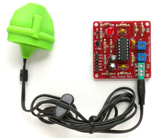
The HRM-2511E sensor is manufactured by Kyoto Electronic Co., China, and operates in transmission mode. The sensor body is built with flexible Silicone rubber material that helps to keep the sensor tightly hold to the finger. Inside the sensor case, an IR LED and a photodetector are placed on two opposite sides and are facing each other. When a fingertip is plugged into the sensor, it is illuminated by the IR light coming from the LED. The photodetector diode receives the transmitted light through the tissue on other side. More or less light is transmitted depending on the tissue blood volume. Consequently, the transmitted light intensity varies with the pulsing of the blood with heart beat. A plot for this variation against time is referred to be a photoplethysmographic or PPG signal. The following picture shows a basic transmittance PPG probe setup to extract the pulse signal from the fingertip.

HRM-2511E as a transmission PPG probe
The PPG signal consists of a large DC component, which is attributed to the total blood volume of the examined tissue, and a pulsatile (AC) component, which is synchronous to the pumping action of the heart. The AC component, which carries vital information including the heart rate, is much smaller in magnitude than the DC component. A typical PPG waveform is shown in the figure below (not to scale).

PPG components shown not to scale
The two maxima observed in the PPG are called Sytolic and Diastolic peaks, and they can provide valuable information about the cardiovascular system (this topic is outside the scope of this article). The time duration between two consecutive Systolic peaks gives the instantaneous heart rate.
Here are the features of Easy Pulse V1.1 sensor module.
- Uses HRM-2511E transmission PPG sensor for stable readings
- MCP6004 Opamp with rail-to-rail output capability for maximum signal swing
- Separate analog and digital outputs
- Potentiometer gain control for the analog output
- Pulse width control for the digital output
- Additional test points on board for analyzing signals at different stages of instrumentation
Circuit diagrams
The following circuit shows the ON/OFF control scheme for the infra-red light source inside HRM-2511E. Note that the Enable signal must be pulled high in order to turn on the IR LED. The photodetector output (VSENSOR) contains the PPG signal that goes to a two-stage filter and amplifier circuit for further processing.

HRM-2511E pulse sensor circuit
The PPG signal coming from the photodetector is weak and noisy. So we need an amplifier and filter circuits to boost and clean the signal. In Stage I instrumentation, the signal is first passed through a passive (RC) high-pass filter (HPF) to block the DC component of the PPG signal. The cut-off frequency of the HPF is 0.5Hz, and is set by the values of R (=68K) and C (=4.7uF). The output from the HPF goes to an Opamp-based active low-pass filter (LPF). The Opamp operates in non-inverting mode and has gain and cut-off frequency set to 48 and 3.4Hz, respectively. In order to achieve a full swing of the PPG signal at the output, the negative input of the Opamp is tied to a reference voltage (Vref) of 2.0V. The Vref is generated using a zener diode. At the output is a potentiometer (P1) that acts as a manual gain control. The output from the active LPF now goes to Stage II instrumentation circuit, which is basically a replica of the Stage I circuit. Note that the amplitude of the signal going to the second stage is controlled by P1. The Opamp used in this project is MCP6004 from Microchip, which is a Quad-Opamp device and provides rail-to-rail output swing.

Stage I filtering and amplification
The second stage also consists similar HPF and LPF circuits. The two-step amplified and filtered signal is now fed to a third Opamp, which is configured as a non-inverting buffer with unity gain. The output of the buffer provides the required analog PPG signal. The potentiometer P1 can be used to control the amplitude of the PPG signal appearing at the output of the buffer stage.

Stage II instrumentation circuit
The fourth Opamp inside the MCP6004 device is used as a voltage comparator. The analog PPG signal is fed to the positive input and the negative input is tied to a reference voltage (VR). The magnitude of VR can be set anywhere between 0 and Vcc through potentiometer P2 (shown below). Every time the PPG pulse wave exceeds the threshold VR, the output of the comparator goes high. Thus, this arrangement provides an output digital pulse synchronous to heart beat. Note that the width of the pulse is also determined by VR. An LED connected to the digital output blinks accordingly.

Digital pulse output circuit
The following picture shows the Easy Pulse Version 1.1 board. The boards were manufactured by Elecrow, a company based in Shenzhen, China, which offers component sourcing, PCB manufacturing and assembly services. It turned out really good. The power supply, Enable, Analog PPG output (AO), and digital pulse output (DO) pins are accessible through the J1 headers. The HRM-2511E sensor connects to the board through a 3.5mm Audio Jack connector (J2). TP1 and TP2 are test pads on the circuit board that are connected to the raw PPG output signal (VSENSOR) and Stage I output (‘a’), respectively.

Closer view of Easy Pulse V1.1
The sensor operation and output waveforms of Easy Pulse V1.1 are discussed in the second part of this article. Click here to read Part 2 of this article.
For US customers, Click here to buy Easy Pulse Version 1.1
Update (05/26/2013)
Easy Pulse version 1.1 boards are now also sold by Elecrow, a China-based company, for $18.50 and ships world-wide. Please visit the following link if you are interested on getting an assembled Easy Pulse V1.1 board at a cheap shipping cost world-wide.
Buy Easy Pulse online
Heart-rate monitor using Arduino and Easy Pulse
|
|
Hello, I bought the EasyPulse 1.1 and I wonder if there is a way to recover the DC part of the signal?
It seems difficult due to the onboard filters?
Thanks a lot!
You are right, it would be hard to recover the dc signal with the current design.
Hi!
Is there a way to keep also the DC component of the signal?
AC/DC ratio is useful in medical research.
Thanks!
Do you have any advice if i want to control the brightness of the LED using a Microcontroller?
Dear Sir
I bought two EasyPulse1.1, DO and LED are constantly producing an artificial rate of 92-95 BPM, even without connecting the sensor. Would You please help me.
Best regards
Bernd
Make sure the sensor jack is inserted all the way into the socket.
Pingback: Pulse Meter Addendum – The Techno-Expert Project
Pingback: Pulse Sensor Proposal – The Techno-Expert Project
hi sir, i will like to ask what is the main difference of every types of easy pulse sensor that ? which version should i choose if i want to get raw ppg signal that i can processed later in Matlab?
*that you developed
Use Easy Pulse V1.1.
https://www.tindie.com/products/rajbex/easy-pulse-sensor-based-on-photoplethysmography/
1.I would like to know whether the PPG signal can be saved and real time use of PPG using matlab is possible with this device?
2.Whether you are providing the arduino board along with this sensor?
3.whether this device has shipment to India?If so how much time it will take?
Geachte Heer of firma lang geleden gekocht de Easy Pulse U 1.1 om mijn kleinzoon te plezieren namelijk hem de
Easy Pulse u1.1 te verbinden met gekleurde leds zodat bij elke hard klopping de leds op de rol oplichten,maar helaas
het schema of printje kan ik nergens meer vinden,zou u mijn kunnen of willen helpen bij voorbaat hartelijk dank
met vriendelijke groet uit Nederland
Hello sir, I bought this sensor from a distributor from Indonesia. The first time I use it was success (in serial monitor, giving random integer output, and Processing giving the graph in correct output). Now I tried to use once more and processing is not giving any output on the display (It’s just blank). Any solution?
can work in 3.7v ?
Yes.
Dear Sir,
There are times when the LED light does not light up and the HRM-2511E sensor seems to be unable to detect my pulse. Is there a way to prevent that from happening?
Thanks!
I have the same problem! What can I do?
Sir,
May I know what is the possibility that causes the led to blink once only when i power up? It does not blink even when I have insert my finger in the sensor.
Thank you.
hi sir..
when i want to install the ”Easy_Pulse_PPG_Analyzer_V1_0.exe” windows says:
‘c:\ProgramData\Oracle\Java\javapath\javaw.exe’
Unspecified error
how can i solve this problem.
please help me…
can you please show us the block diagram of this project
i want to purchase this in india . can you send this . 10 pcs
You can buy from here:
http://www.elecrow.com/cooperated-designers/embedded-lab.html
please help, how example code for adruino??, i have tried, but i get the same data. .
Pingback: Tindie Blog | Easy Pulse Plugin : An Open Source Pulse Sensor
Pingback: Heart Beat Sensor |
Is it possible to connect this device to matlab directly to get real-time data.? i have an icp12 device that i use to currently connect it to pc and to derive data through smartdaq software. please help.
A nice one, from all i have read about it, my main question basically is, that am confused on which is the main circuit diagram of the easy pulse detector?
i am a student working on PPG signal. i am using Easy Pulse sensor 1.1. It provides good results. Can you tell me why we required two stage OF SAME LOWPASS AND highpass filter.or can we change the cutoff frequency and gain???
sir, i wanted to make this your technology as my final year project, please how can you help me
my ID: mbrktofa57@gmail.com
Can I use either matlab or labview using instrument control to display d pulse on a pc instead of ppg cos I want to work with it for my project
Will any 3.5 mm Audio Jack work for this board? I’m having difficulty picking a audio jack.
Hi Rajenda,
Thanks so much for making your excellent project open source.
I bought an Easy Pulse Ver 1.1 and it works beautifully right out of the box – nice job!
I’m currently experimenting with recreating it on a breadboard (I tried that with the original version of Easy Pulse, but wasn’t very successful) but wanted to know if I could use the TCRT1000 sensor instead of the HRM-2511E ? for this new project? – I realize that it’s not as stable as the HRM, but technically, I think if I swap the 10K for 1K on the enable & the 120 Ohm for a 150 Ohm resistor on the collector that should be OK for the wiring.
Would the Vsensor output be adequate enough to operate the remaining device? Maybe some adjustments on the 10K pots helps? – Big grey area for me!
Hope to hear your thoughts.
Thanks,
Rich.
p.s. Sorry, I just realised I misspelt your name.
For TCRT1000, you can use the same circuit with some modifications that you have mentioned, like increasing the 120Ohm by 150 Ohm, and so. But the output would be less stable.
Excellent, thanks for the confirmation on that!
Thinking about it, if I wanted to by a couple of the HRM-2511E modules, are they available separately? – I’ve found them on Alibaba, but they need a min order of 1000 units.
I’m wanting to recreate your project into an artwork where the DIY etched circuit is aesthetically part of the work & will use the TCRT1000 for one of them, but may switch back to the HRM-2511E for more stability.
Also, would you happen to have the wavelength / specs / model number of both the LED and Photosensor in the HRM-2511E? – maybe I can get those on Mouser and create my own finger cup.
Again, many thanks for your help.
Rich.
It is possible to connect this prototype to a myDAQ device in the VCC pin?
It would be possible to receive the PCB design of this Easy Pulse?
Hi, Im trying to integrate the pulse sensor into a project I’m doing. Is there a schematic I can look at, I was hoping to create it with some modifications. Thanks!
i can simulate the output with labview using DAQ simulation circuit
Hi, i received the sensor and it’s work!
i have a question about the sensor, it is possible to connect VCC heart sensor to I/O arduino digital as a an ouput? because i need to stop the sensor after 1 hour…
thanks for your help
Hi Julien,
No you can’t power the sensor with Arduino output pin. The sensor requires ~130 mA current for operation, which cannot be delivered by an output pin. There is a EN pin on the board which can be connected to Arduino pin to activate/deactivate the pulse sensor.
thanks for answer and explication, yes 130ma exceeds the limit of the ouput…
If i understand i remove the jumper between vcc and en and i connect en to i/o digital ouput…thanks
True.
Hi, i am thinking to buy this board… I would like to add some other circuit to make the hearthbeat audible; to a mini jack female connector. It’s an easy job with this board? Or it only makes like not audible digital pulses or trigs?. I can use an Arduino or maybe a Raspberry Pi if it’s needed… Thanks!
The output will require a current amplifier to drive a speaker for audio sound.
Hi! my name is Alan can you tell me, What is the zener diode model you use?
thanks
Can I use Lth 1550-01 in place of the sender shown???
Why are v using Vref using zener?? Can Vref be grounded??
Hi can i use this circuit for transmission mode of operation. i want to find the arterial pulse to detect stiffness of artery
Does anyone know how to get this wired up to a Rasp Pi?
Pingback: ماژول سنسورایزی پالس - سنسور ضربان قلب
Awesome article sir…
it worked in first attempt…
thank you very much..
currently trying to make a smaller version of this circuit. the SMD packages for zener diodes (from what I’ve seen) have a voltage of 2.4V instead of 2V. Will this make a different to the reference voltage?
would you mind to explain – why you need 2 stage filter the signal while only one can do , why the stage 2 is excatly the same with stage 1
Can u give only green sensor please?
Please tell me, Can i use Lm358 instead of MCP 6004, this is not available , or any other suitable amplifier.
Please reply soon as posible,
Can u tell me the referred amp instead of MCP 6004
Mine worked perfectly with LM 324…
Go ahead as circuit will work with any oppamp as it does not involve very high frequencies…
Hi! im Alan, can you tell me, What is the zener diode model you use?
Hi! Would you mind writing the software for pic microcontroller? thank you very much! 🙂
Have a good day!
Hi, I would like to get the CAD file to check if the PPG Sensor can be used for a project that I’m developing. How can I contact the author?
I’d like to post a comment on the Easy Pulse. I can’t locate any product review page, so this will have to serve. I liked the device, it is quite professionally constructed, and is easy on the pocketbook. I can use the device, and found the inventor, Raj., to be top-notch for customer service and satisfaction. He is quite personal about helping the customer and goes “the extra mile” to do it. I’ve not see this very often.
I was wondering if I could extract pulse wave velocity from the waveform of the Easy Pulse 1.1. There is literature describing ways in which that can be done:
http://m.qjmed.oxfordjournals.org/content/95/2/67.long
http://hyper.ahajournals.org/content/51/1/112
http://www.pulsecor.com/augmentation-index.html
Which does not mean that the signal is present clearly enough in the peripheral capillaries to be measured.
I’ve had no problem in extracting a double-peaked signal from the Easy Pulse 1.1, but I have nothing to validate it against.
I also bought two Easy Pulse 1.0’s – which have the advantage of being reflective, rather than transmissive, so I had thought I might be able to use it at the carotid and femoral. With two signals at two locations, calculating the velocity would be simple, and I could use that to validate the calculations I was extracting from the Easy Pulse 1.1’s waveform.
Unfortunately, I’ve not been able to get a signal out of the 1.0’s, except at the fingertip. At the fingertip, I get a signal, if I’m careful. I’ve been unable to get a clean signal anywhere else on the body.
Anyone have any ideas? Either in how to make the 1.0’s, work, or how to make the 1.1’s work on the trunk, or of some other way of detecting the pulse?
Thanks would be appreciated.
Hi Jeff,
Did you manage to get the pulse wave velocity using easy pulse? We are working on a design project which involves the calculation of the pulse wave velocity in order to determine if the user has peripheral arterial disease.
Let me know. 🙂
The favor will be returned 😀
Could anybody that is monitoring this website advise me regarding the Easy Pulse 1.1 circuit I just bought and received today? I need to know exactly which pins I should hook the 9v battery to. I’m not quite an intermediate electronics student and I need to be certain I am hooking the battery wires correctly. Could anyone assist me please, and if not, give me contact information on who can help?
Thank you,
Adam
sorry, i purchased the easy pulse device, but didnt get a data sheet with it , i need to knw the equivalent heart beat to the voltage e.g dose 60bpm equal to 5V?
Can i send the o/p signal to GSM module?
hey everyone I am using the easypulseV1.1 to interface with the c8051f020 microcontroller. I connected the digital output from the sensor to the T1 pin with timer 1 configured as an external counter. The problem I have is the microcontroller is counting up to 800 high to low transistions in a 1 minute test. Is it possible to clean up this signal?? any help would be greatly appreciated?
Hi Gerard,
Try something like this: Once you detect low-to-high or high-to-low transition, wait for 50 ms before counting another transition. This should clean up the transient behavior if there exists any.
Can you use this in reflection rather than transmission. I would like to use it for an undergraduate project but it needs to work in reflection. I guess this is similar to Patryk’s question.
thanks
Can i replace HRM2511E sensor to TCRT1000?
Hi, Could I buy only IR sensor parts? (green module and dc-jack(?) line)
May i know whether this easy pulse v1.1 can be connected to Netduino Plus?
may i know whether this easy pulse version 1.1 can be connected to Netduino plus?
Pingback: BLOG | Introducing Easy Pulse Version 1.1 Sensor
hiii Mr. ROjbex i need to discuss with you regarding this technology as i trying to develop this kind of technology with few more modifications i hope u can help me so please contact me sir.
my id : ramya.kirthe@gmail.com
It would be great if you could put this green part into wrist. Maybe you can convert it to run on the wrist? I need this stuff for running:)
hi, may i know do you provide any programming code on PIC for this project? can i change to pic18f4550? as i need to interface this system with laptop using USB later.
Pingback: Easy Pulse PPG sensor for measuring pulse rate | Make, Electronics projects, electronic Circuits, DIY projects, Microcontroller Projects - makeelectronic.com