Introducing Easy Matrix: A cascadable 8×8 LED dot matrix display module
|
|
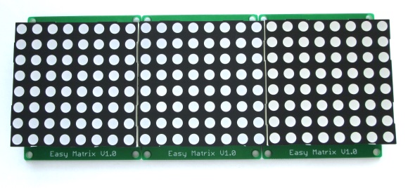
Easy Matrix is an easily cascadable 8×8 monochromatic LED dot matrix display module with onboard MAXIM’s MAX7219 LED driver chip. The MAX7219 allows you to drive the LED matrix using only three I/O pins of Arduino or any other microcontroller. The LED matrix module used in Easy Matrix has a bigger dot size (5mm) and has the overall display dimensions of 60.2mm x 60.2mm (2.4″x2.4″). It is easily cascadable in series with the help of precisely aligned male and female header pairs located on the left and right sides of the display module. With lots of freely available Arduino libraries for MAX7219 chip, this module is easy to use in any Arduino project for displaying basic text and animation.

Easy Matrix: Cascadable LED matrix display module
Description
The Easy Matrix PCB dimensions are 60.5mm (2.4″) x 75.0mm (2.95″) and has 3.5mm mounting holes at its four corners. It uses a male (J1) and female (J2) headers for cascading multiple modules in series. The MAX7219 data input and control signals are accessible through J1 header on right side. The J2 header provides the MAX7219 serial data output and control signals to another Easy Matrix module cascaded to its left. Two 1×8 female headers are used as sockets to hold the LED matrix module with A-type polarity, which means the rows are common-anodes and the columns are common-cathodes. The picture below shows an Easy Matrix display PCB with all the electronics components assembled. One of the header socket is marked with a “circle with 1” to indicate where the pin number 1 of the LED matrix display should be inserted.
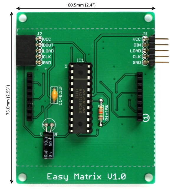
Easy Matrix display board components
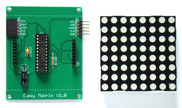
Easy Matrix module
Features
- Operates at +5V
- 16 brightness levels controlled through software
- Easily cascadable (recommended maximum 8 modules in a cascade)
- Supports both Mark Ruys’ Max72xxPanel (Adafruit’s GFX library is also required) and MaxMatrix libraries.
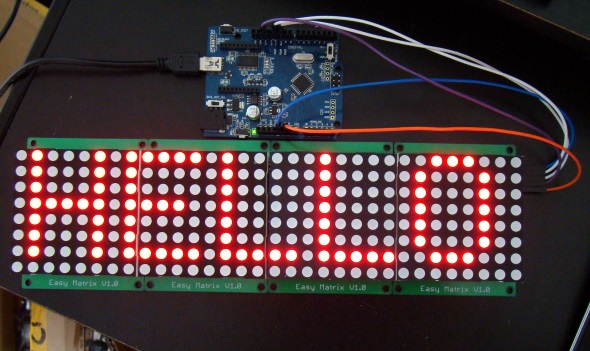
Four Easy Matrix modules cascaded together and driven by Arduino Uno
Demo project: Portable Bluetooth-enabled Scrolling LED Matrix Display
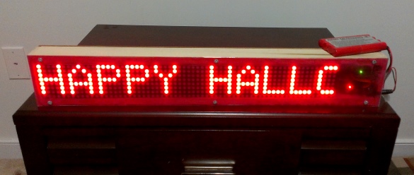
Scrolling LED matrix demo
|
|
where I can buy the easy matrix v1.0?
From the following link if you are in US:
https://www.tindie.com/products/rajbex/easy-matrix-a-cascadable-led-matrix-module-kit/
Please l want to learn how to write programs for microcontrollers
Im willing to pay someone that can get me a working prototype of this project! Please email me at bonzairios@gmail.com if interested. Thanks!
Good morning. I’m having some difficuly understanding how the display ” SURE ELECTRONICS P4 32X8 3208 RED LED DOT MATRIX UNIT BOARD SPI LIKE” Arduino UNO works. – I would like to add some buttons and potentiometers to the system. For exampe: by pressing the 1 st button the name display with the memorised name could light up per minimum 30 seconds and so on for the entries on the other buttons. – I would like to know how to add two potentiometers: one to adjust the speed of sliding and one to adjust the time. Thank you in advance. Looking forward to your kind reply. Best regards
Buen proyecto felicitaciones. Quisiera pedir el favor y me ayude tengo un modulo MAx 7219 con los pines VCC GND DIN CS y CLK pero no puedo conectarlos a ARDUINO UNO.Tengo confusiones. me podría indicar a que pines de arduino uno van conectados? Saludos desde Colombia y Gracias por su orientacion
i want to be your distributor in nigeria or do you have one here
Hello I need to correct a bit of the author.
I saw the MAX7219CNG is a common cathode driver thus the LED Matrix needs to be:
Rows are Common Cathode and the columns Common Anode.
I ordered 90x Common Cathode LED Matrix display and 10x Common Anode Display.
The Common Cathode worked and the Common Anodes did not work.
Thanks
Hello there
I have tried your circuit for cascading LED Matrix. It is working but I have some troubles trying to save it into the EEPROM and reading it back so that once the device is switched off and back on again, the data displays automatically on the LED Matrix again.
It is sucesfully stored into the EEPROM and saved bit by bit into the address, I just need to re initialize it.
Could you please have a look in helping me if possible? I would appreciate it very much.
The link to the modified code is as follows:
http://forum.arduino.cc/index.php?action=profile;area=showposts;u=361498
or
http://forum.allaboutcircuits.com/threads/arduino-led-matrix-eeprom.110071/
Thank you in advance!