Lab 7: PIC Timers and Counters (Part 1)
|
|
Description
PIC microcontrollers are equipped with one or more precision timing systems known as Timers. They can be used to perform a variety of time precision functions, such as generating events at specific times, measuring the duration of an event, keeping date and time record, counting events, etc. The main component of a timer module is a free running binary counter that increments for each incoming pulse. Since it runs independently, it can count pulses concurrently with the main program execution. A PIC16F688 microcontroller has two built-in hardware timer modules: Timer0 and Timer1. Today’s lab lesson will explore the functionality of the Timer0 module.
Required Theory
The fundamental concept of a timer/counter module is discussed in Timers and Counters. It is simply an independent binary counter that can be configured to count instruction cycles or to count external clock pulses. The Timer0 module in a PIC16F688 microcontroller is an 8-bit synchronous counter that stores the value for the counter in the special function register called TMR0. This register can be read or written at any time by software. If you write a value to it, the counter will start incrementing from there.
When the Timer0 module is driven by the processor’s instruction clock, it is said to operate as a timer because it increments at a constant rate (defined by the processor clock) and if you know the number of pulses counted, you can derive how much time has elapsed. The Timer0 can also count external pulses arriving at the RA2 pin (11), which has the alternate name T0CKI (Timer Zero Clock Input). While counting the external pulses, it is said that it operates as a counter. We will discuss the two modes of Timer0 separately.

Block diagram of Timer0 Module (Source: Microchip)
Timer mode
Timer mode is selected by clearing the TOCS bit (OPTION register, bit 5). In timer mode, the TMR0 register increments every instruction cycle. As an 8-bit register, TMR0 can count from 00 to FF (255). When it reaches its maximum value, FF, and is incremented further, it rolls over to 00. This register overflow is recorded by the T0IF (Timer0 Interrupt Flag) bit of the INTCON (Interrupt Control) register by being set to 1. The T0IF bit set can trigger an interrupt (known as Timer0 Interrupt), if enabled. [An interrupt is an asynchronous signal calling for processor attention. It tells the microcontroller to drop whatever it’s doing and go to a predefined place (the interrupt service routine or ISR) when a certain event occurs. We will discuss it more in upcoming lab sessions]. The Timer0 interrupt is enabled by setting the T0IE bit (Timer0 Interrupt Enable) of the INTCON register along with the Global Interrupt Enable (GIE) bit. This interrupt would be the indication of the time out and will occur on the every overflow of the TMR0 register. The TOIF bit must be cleared by the interrupt service routine so that the timer interrupt can take place again.
Suppose, if you are running a PIC with a 4 MHz clock, the instruction clock will be 1 MHz (1 instruction cycle = 4 clock cycles, for PIC). The counter would then be clocked every 1 ?s exactly. That means, the Timer0 will take 256 ?s to count from 0 to 0. By preloading the TMR0 register with a suitable value, a smaller timer interval could be selected, with time out indicated by the timer interrupt. For example, if you preload the TMR0 register with the value 206, the Timer0 overflow would occur after 50 ?s.
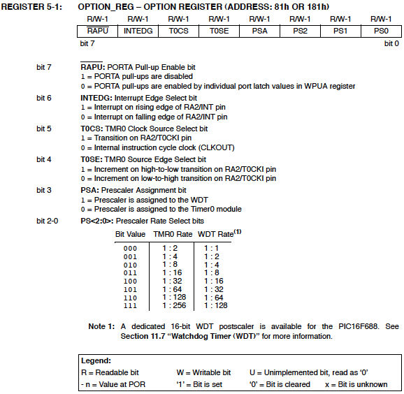
Besides, an eight bit programmable divider, known as prescaler, is also available to measure a longer time period. The prescaler is a dividing circuit between the clock source and the timer, and it divides the input frequency by one of eight binary values between 2 and 256. With 1 MHz instruction clock, the maximum timer period would be 256 x 256 ?s = 65.536 ms, corresponding to the prescaler value of 256. The prescaler values are software selectable through PS0, PS1, and PS2 bits of the OPTION register. In order to use the prescaler with the Timer0 module, the PSA (Prescaler Assignment) bit of the OPTION register must be cleared. If the PSA bit is set, no prescaler will be assigned to the Timer0 module. The individual bits of the OPTION and INTCON registers are shown below.


Source: PIC16F688 Datasheet from Microchip
Counter Mode
Counter mode is selected by setting the TOCS bit in the OPTION register. In this mode, the Timer0 module counts the external clock pulses applied to its RA2/T0CKI pin. The counter will increment either on rising or falling edge of the clock pulses, which is software selectable by the T0SE (Timer0 Source Edge) bit of the OPTION register. If you set the T0SE bit, the timer will increment on the falling edge of every clock pulse arriving at the RA2/T0CKI pin. Again, the range of the counter can be extended by the use of the prescaler.
The maximum clock frequency at the T0CKI input is limited by the synchronization requirement with the internal clock. Each machine cycle (or instruction cycle) for a PIC microcontroller consists of four clock cycles, which are named as Q1, Q2, Q3, and Q4. The synchronization of T0CKI with the internal clock is accomplished by sampling the prescaler output on the Q2 and Q4 cycles of each machine cycle. Therefore, the external clock signal at T0CKI should remain high or low for at least half of the duration of the machine cycle (which is 2Tosc, Tosc is the period for the main oscillator), plus an additional resistor-capacitor delay of 20 ns. This determines the minimum value of the pulse width that enters through the T0CKI pin. The minimum time period of the input clock pulse is, therefore, 4Tosc + 40 ns, and the maximum frequency will be the reciprocal of this.
For example, if the main oscillator frequency is 4 MHz (Tosc 0.25 ?s), the machine cycle will be 4 x Tosc = 1 ?s long. An external clock signal going directly into the counter (without the prescaler) should be high for at least 2Tosc+20 ns = 520 ns and low for at least the same time, giving the total time period of 520 x 2 = 1040 ns. Therefore, the limit for maximum input frequeny would be 1/1040 ns = 961.5 KHz. If the prescaler is used, the electrical specification of PIC16F688 says that the external clock input must be high and low for at least 10 ns, which gives the maximum countable frequency through T0CKI pin equal to 50 MHz. Read Microchip’s tutorials on Timers: Part 1 and Part 2 for further details.
Experimental Setup and Software
After reviewing the theory, lets think about doing some experiments with the Timer0 module. First, we will create an approximate 1 sec delay using the Timer0 module as a timer. The PIC16F688 runs at 4 MHz clock frequency, so the duration of a machine cycle is 1 ?s. To generate 1 sec delay interval, the timer should count 1000000 machine cycles. If we use the prescaler value of 256, the required count will be reduced to 3906. Now, if we preload the TMR0 with 39, it will overflow after 256-39 = 217 counts. This gives the required number of overflows to make 3906 counts = 3906/217 = 18. With this setting, after every 18 overflows of TMR0 register (preloaded with 39), an approximate 1 sec interval is elapsed. The software below implements this to flash an LED with an approximate 1 sec interval.
/*
Lab 7: 1 sec timer using TIMER0
Internal Oscillator @ 4MHz, MCLR Enabled, PWRT Enabled, WDT OFF
Copyright @ Rajendra Bhatt
Nov 18, 2010
*/
// Define LED connection
sbit LED at RC0_bit;
unsigned short Num;
// Interrupt service routine
void interrupt() {
Num ++; // Interrupt causes Num to be incremented by 1
if(Num == 18) {
LED = ~LED; // Toggle LED every sec
Num = 0;
}
TMR0 = 39; // TMR0 returns to its initial value
INTCON.T0IF = 0; // Bit T0IF is cleared so that the interrupt could reoccur
}
void main() {
CMCON0 = 0x07; // Disable Comparators
ANSEL = 0x00; // Disable analog channels
TRISC = 0x00; // PORTC O/P
LED = 0;
Num = 0;
OPTION_REG = 0x07; // Prescaler (1:256) is assigned to the timer TMR0
TMR0 = 39; // Timer T0 counts from 39 to 255
INTCON = 0xA0; // Enable interrupt TMR0 and Global Interrupts
do {
// You main programs goes here
} while(1); // infinite loop
}
The circuit setup is the same as Lab 1: Flashing an LED. The LED is driven through RC0 pin.


Circuit setup for flashing LED using Timer0 module
Note: The 1 sec delay that we just created is not very accurate because of the following reasons:
- In this example, the PIC16F688 microcontroller was operated with the 4 MHz internal RC oscillator, which is not highly accurate and stable. For better accuracy, an external crystal oscillator must be used.
- The timer program was written in a high-level language, so we don’t know exactly how the program looked like after being compiled. For an accurate hardware timer, the programming must be done with assembly language, and any instruction that can affect the TMR0 read/write operation, should be accounted as it may introduce additional delay.
Next, the Timer0 module will be used as a counter to count the external clock pulses through RA2/T0CKI pin. The external clock source will be derived from the mains AC supply. The mains AC is 120V, 60 Hz sine wave signal. It will be first stepped down to 9 V, 60 Hz signal using an AC wall adapter. Before applying it to the T0CKI pin, it must be rectified and the peak voltage should be chopped down to +5V. The following circuit will convert the 9 V, 60 Hz AC voltage to an approximate +5 V square wave suitable for the T0CKI input.

The output square wave will be connected to the RA2/T0CKI pin of the PIC16F688 microcontroller. The TMR0 will start from 0 and count the incoming pulses for 1 sec. The result will be displayed on the LCD screen. The number of pulses per second is the frequency of the incoming signal, which is 60 Hz. The circuit diagram for the microcontroller and LCD part is shown below.


Counter circuit setup on the breadboard
Programming sequence involves initialization of ANSEL, CMCON0, and OPTION registers. The T0CS bit in the OPTION register must be set to operate the timer module as a counter.
/*
Lab 7: Timer0 as a counter
Internal Oscillator @ 4MHz, MCLR Enabled, PWRT Enabled, WDT OFF
Copyright @ Rajendra Bhatt
November 18, 2010
*/
// LCD module connections
sbit LCD_RS at RC4_bit;
sbit LCD_EN at RC5_bit;
sbit LCD_D4 at RC0_bit;
sbit LCD_D5 at RC1_bit;
sbit LCD_D6 at RC2_bit;
sbit LCD_D7 at RC3_bit;
sbit LCD_RS_Direction at TRISC4_bit;
sbit LCD_EN_Direction at TRISC5_bit;
sbit LCD_D4_Direction at TRISC0_bit;
sbit LCD_D5_Direction at TRISC1_bit;
sbit LCD_D6_Direction at TRISC2_bit;
sbit LCD_D7_Direction at TRISC3_bit;
// End LCD module connections
// Define Messages
char message1[] = "Frequency= Hz";
char *freq = "00";
void Display_Freq(unsigned int freq2write) {
freq[0] = (freq2write/10)%10 + 48; // Extract tens digit
freq[1] = freq2write%10 + 48; // Extract ones digit
// Display Frequency on LCD
Lcd_Out(1, 11, freq);
}
void main() {
CMCON0 = 0x07; // Disable Comparators
ANSEL = 0x00; // Disable analog channels
TRISC = 0x00; // PORTC O/P
TRISA = 0b00001100; // RA2/T0CKI input, RA3 is I/P only
OPTION_REG = 0b00101000; // Prescaler (1:1), TOCS =1 for counter mode
Lcd_Init(); // Initialize LCD
Lcd_Cmd(_LCD_CLEAR); // CLEAR display
Lcd_Cmd(_LCD_CURSOR_OFF); // Cursor off
Lcd_Out(1,1,message1); // Write message1 in 1st row
do {
TMR0=0;
Delay_ms(1000); // Delay 1 Sec
Display_Freq(TMR0);
} while(1); // Infinite loop
}

References:
1. Timer0 Tutorials from Microchip 2. PIC Microcontrollers (second edition) by Martin Bates|
|
I am trying to figure out how you set up your timer:
https://embedded-lab.com/blog/another-programmable-relay-switch-using-pic-mcu/
I would like to change it to counting and displaying seconds and minutes instead of minutes and hours but I am not seeing it in either your C file or your asm file. I see TMR0 and preset to 39 but not seeing how it divides the time. I assume I would need to just divide that by 60 (or preload TMR0 with some higher value than 39.
Can you get me pointed in the right direction?
Thank you.
i want to know the programme pulse encoding counter displayed in lcd using pic18f452
how do we know the minimum delay can the timer make?
It’s very useful..thanks for ur valuable information.????
It’s very useful for students..thanks for information.
can u post how to measure speed using pic micro controller?( program required)
Sir, I want to make Frequency Counter in Khz will u plz provide mikro c code n circuit if possible. THANK YOU VERY MUCH.
can i ask somthing.. how to add timer0 control to my program ? void main()
{
short duty1 = 16; //initial value for duty
TRISD = 0xFF; //PORTD as input
TRISC = 0x00; //PORTC as output
TRISB = 0x00; //PORTB as output
PORTB = 0x02; //Run motor in anticlock wise
PWM1_Init(1000); //Initialize PWM1
PWM1_Start(); //start PWM1
PWM1_Set_Duty(duty1); //Set current duty for PWM1
while (1) // endless loop
{
if (PORTD.F0==0) //Checking the button pressed or not
{
Delay_ms(1);
duty1++; // increment duty cycle
PWM1_Set_Duty(duty1); //Change the duty cycle
}
if (PORTD.F1==0) // Checking the button pressed or not
{
Delay_ms(1);
duty1–; // decrement duty cycle
PWM1_Set_Duty(duty1);
}
Delay_ms(10);
} }
Hi,
Mr Raj please tell me from where the count 39 came
Hello, very well written article on counting. It clarified a ton for me.
I have two questions though; you said that because the code was written in a high level language, and because the internal clock was used, that the timer for this circuit is not particularly acurate; does this mean that the watchdog timer in a PIC is also relatively inaccurate? Is there any sort of rough guess to what the error is?
Also, would this apply to something like a counting a Beat frequency oscillator? It too, would be as inaccurate?
Thank you.
The timer is well explained and understood but there is no clue about how the counter part of the program works.
Any change of explaining it?
What is this and how does it work?
freq[0] = (freq2write/10)%10 + 48; // Extract tens digit
freq[1] = freq2write%10 + 48; // Extract ones digit
Thanks,
Jack
Hi Jack,
Sorry about the confusion. Which part of counter is not clear to you? I know there is some formatting error in the text which occurred after I switches the template of my blog last year. But I will try to clarify if you tell me specifically.
Regarding your second part, we extract individual digits from a number (freq2write) and convert it to ASCII character by adding 48. The LCD requires ASCII character for display. For instance, if you want to display ‘5’ on an LCD, you have to send 5+48 = 53 to LCD, which is a ASCII code for number 5.
I guess I never came back to see your response and have bungled around on my own to figure it out. Actually, this morning I finally got it to do what I wanted which was simply to count inputs and display the count. A simple revolution counter.
My next step is to implement this with Timer1 and I thought you had a tute on that but don’t see it. I want to do the same thing but count to 65K.
I have done most of these things in asm and 7 seg displays but I am trying to learn C because the LCD is so much easier.
BTW, your comment says 1:1 for the prescaler. Is that a typo or is there some way to do this with WDT?
Nice to know you still support your tutorials. Thanks for the heap.
Jack
Here is my variation on your program…
/*
Lab 7: Timer0 as a counter
Counts to 255/2 9/12/15 js
modified for 16f268 js 8/4/2015
Modified for 3 digits 8/10/2015 js
Internal Oscillator @ 4MHz, MCLR Enabled, PWRT Enabled, WDT OFF
Copyright @ Rajendra Bhatt
November 18, 2010
*/
// LCD module connections
sbit LCD_RS at Rb4_bit; //Pin 10
sbit LCD_EN at Rb5_bit; //PIN11
sbit LCD_D4 at Rb0_bit; //PIN6
sbit LCD_D5 at Rb1_bit; //PIN7
sbit LCD_D6 at Rb2_bit; //PIN8
sbit LCD_D7 at Rb3_bit; //Pin 9
sbit LCD_RS_Direction at TRISb4_bit;
sbit LCD_EN_Direction at TRISb5_bit;
sbit LCD_D4_Direction at TRISb0_bit;
sbit LCD_D5_Direction at TRISb1_bit;
sbit LCD_D6_Direction at TRISb2_bit;
sbit LCD_D7_Direction at TRISb3_bit;
// End LCD module connections
sbit Pin3 at Ra4_bit;
// Define Messages
char message1[] = “Revs = “;
char *freq = “000”;
void Display_Freq(unsigned int freq2write) {
freq[0] = (freq2write/100) + 48 ; //huns
freq[1] = (freq2write/10)%10 + 48; // Extract tens digit tens
freq[2] = freq2write%10 + 48; // Extract ones digit units
// Display Frequency on LCD
Lcd_Out(1, 11, freq);
}
void main() {
CMCON = 0x07; // Disable Comparators
TRISb = 0x00; // PORTC O/P
TRISA = 0b00111000; // RA4/T0CKI input, RA3 is I/P only PIN3
OPTION_REG = 0b00100000; // Prescaler (1:2), TOCS =1 for counter mode
Lcd_Init(); // Initialize LCD
Lcd_Cmd(_LCD_CLEAR); // CLEAR display
Lcd_Cmd(_LCD_CURSOR_OFF); // Cursor off
Lcd_Out(1,1,message1); // Write message1 in 1st row
do {
Display_Freq(TMR0);
} while(1); // Infinite loop
}
Hi John,
I am glad you figured out the problem. Regarding the prescaler, it is confusing indeed. But if you see my code, I have defined OPTION_REG = 0b00100000, where PSA but is set to 1. If you do this, the prescaler is assigned to WDT, and Timer0 gets no prescaler, which means it is 1:1. This is described in the datasheet of PIC16F688 in more details. Otherwise, if you assign the prescaler to Timer0 (by clearing PSA to zero), the minimum prescaler is 1:2.
can you please give the exact formula for the computation? Its hard to understand.. BTW.,thank you for your tutorial
hi sir !!!
how to count if i want interrupt after 2 second???
i didnt understand at 1 second, please reply soon.
thanks.
Hello.
i am working on pic18f67j11 ,i am getting difficult on generating 1sec delay using timer can any bdy help me in this
Regards,
Bandenamaj
Hello.
i am working on pic18f67j11 ,i am getting difficult on generating 1sec delay using timer can any bdy help me in this
Regar
please sir
may you help me the codes for pic AT89S52 so as to count pulses from energy meter chip ADE7751 and to display to the LCD 16X2 as the electrical units
please sir may you help me the codes for pic AT89S52 so to count pulses from the energy meter chip ADE7751 , so as to display the units in LCD 26×2 as energy meter
Dear RB,
why don’t you compile all of your Tutorials in to single PDF
Regards
Bhavani Sankar Appalla
I am doing a project on density based traffic light control using PIC microcontroller and IR sensor,I doesnt know how to calculate the time delay from the vehicle count,please help me ad send me the source code
nice work
i want to get an alert signal at 48hz and at 52hz for saving the load from the fluctuation of generator frequency of rnewable energy resources.
dear sir request provide c code for 12 led chaser with comet tail effect ( i mean followed led to be faded and off like sweeping pattern)
Raj?
PSA = 0
PS0 = 0
PS1 = 0
PS2 = 0
the prescaler would be 1:2 ???
thank you!
marC:)
yes !!!!
sorry wrong : 15, 625 machine counts
with prescaler 1:64, 15 625 / 25 = 625 count
is it correct?
thank you!
marC:)
Let’s say i use the prescaler 1:64 for 1 second delay.
it means : 1,000,000 / 64 = 15 625 counts. (cycles machine)
by preloading a value of 39 in TMR0.
it will overflow after : 64 – 39 = 25 counts
Is it correct Mr. Raj?
Did i understand ?
thank you so much!
marC:)
Thank you Mr. Raj it clears up a lot of things! 🙂
have a good day! 🙂
marC:)
HI Raj!
I don’t understand th enumber 3906 , if prescaler = 1:256??
can you explain me please??
thank you!
marC:)
In order to get 1s interval, we need 1000000 machine cycles (each machine cycle is 1us at 4.0 MHz clock). If we use prescaler 1:256, the timer clock is further divided by 256. So, we need 1000000/256 which is approximately 3906 counts.
Hi Mr Raj!
I tried this code :
void interrupt() {
Num ++;
if (Num == 840) {
count = count + 1;
Display_Data();
Num = 0;
}
TMR0 = 39; // TMR0 returns to its initial value
INTCON.T0IF = 0; // Bit T0IF is cleared so that the interrupt could reoccur
}
but it never happens … 18 happens but 840 for 1 min doesnt happens at all 🙁
please help me Mr. Raj!
TMR0 = 39; // TMR0 returns to its initial value
INTCON.T0IF = 0; // Bit T0IF is cleared so that the interrupt could reoccur
}
if (Num == 840) {
count = count + 1;
Display_Data();
Num = 0;
}
Marc,
Num is defined as unsigned short in the original program and therefore it cannot have value over 255. You should change it to unsigned int at the top of the program and recompile.
For a kitchen timer the prescaler would be 1:1, OPTION_REG = 0b00101000; // Prescaler (1:1), TOCS =1 for counter mode ?
thank you!
marC:)
Hi Raj! Thanks for the tutorial.. but why 2 OPTION_REG ?
OPTION_REG = 0x07; // Prescaler (1:256) is assigned to the timer TMR0
OPTION_REG = 0b00101000; // Prescaler (1:1), TOCS =1 for counter mode
what is the difference??
Sir,
In counter part, why we loaded 39 in TMR0? means we understand that 39 is to be loaded?
does this project works with 120VAC?
thanks!
marC:)
Yes, but it requires a 9V step down transformer.
For a AC voltage of 120 VAC does it work?
thanks!
marC:)
Pingback: [Moved] how to generate 1,2,4,7 hour of delay in mikro c
Hello R-B
thanks for this tutorial, I’ve done it on Proteus and it work 🙂
but my problem now is to implement it using PIC18 (PIC18F458), I’m using CMCON (disable comparator), ADCON0 (disable analog ch) and T0CON (as PIC18F458 don’t have OPTION_REG).
In MikroC pro it seem the program question me why TMR0 is undeclared but when check on orignal program (by you) TMR0 is not undeclared but no error!?
I wonder how to solve this ?
Thank you and regard
Can you please explain this line of above code
Display_Freq(TMR0)
Display_Freq(unsigned int) is a user defined function subroutine that displays the passed result onto the LCD screen. This function is written in the program before the main program.
Pingback: 16-bit Timer for PIC18F452
Thanks a lot.
* char message1[] = “Frequency=(3 spaces here) Hz”;
By the way, I have one more question.
If I changed it to
char message1[] = “Frequency= Hz”;
char *freq = “000”;
void Display_Freq(unsigned int freq2write) {
freq[0] = (freq2write/100)%10 + 48;
freq[1] = (freq2write/10)%10 + 48;
freq[2] = freq2write%10 + 48;
Lcd_Out(1, 11, freq); would it mean it would count up to 3 digits?
Thanks a lot.
This will display the three digits of the counter value.
Hi sir,
I have got it. Thanks again.
If the prescaler is used, the electrical specification of PIC16F688 says that the external clock input must be high and low for at least 10 ns, which gives the maximum countable frequency through T0CKI pin equal to 50 MHz.
Hi sir,
Why is it 50Mhz?
Would you please show me?
Thanks a lot
@simon,
Time period of maximum frequency signal, T = TH + TL = 20 ns. This gives the maximum frequency = 1/T = 50 MHz.
what software are you using to draw the circuits for these tutorials?
Matiko,
I made these circuits with Microsoft Powerpoint.
i like the explanations, as for me, i have read some articles related to computer engineering like cpuville.com
that and this website has helped me to ‘see’ the complete picture.
thx a bunch
thanks a lot ….. it is very useful explanation for timers/counters ….
Pingback: Electronics-Lab.com Blog » Blog Archive » Tutorial on PIC timers and counters