Tag Archives: breadboard


DIY plug-in modules to make microcontroller breadboarding easier

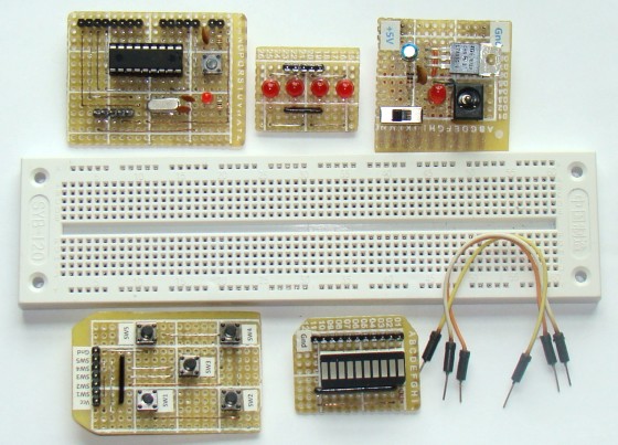
Breadboards are a great tool for prototyping and testing electronics circuits. Here I am sharing with you some plug-in modules that I once made to make my breadboarding life easier. I have used these modules many times in the PIC experiments described in this blog. These modules  serve very common functions that are required in most microcontroller circuits. Their use not only reduces the number of wire connections on breadboard, but also expedites prototyping and makes debugging of the circuit easier.

Plug-in modules for easy microcontroller breadboarding

Read more

Lab 1: Flashing an LED

Description

Today is our first session in PIC microcontroller lab, and we will begin with an experiment that flashes an LED on and off. While this looks very simple it is the best project to start because this makes sure that we successfully wrote the program, compiled it, loaded inside the PIC, and the circuit is correctly built on the breadboard.

In this lab session we will connect an LED to one of the port pin of PIC16F688 and flash it continuously with 1 sec duration.

Required Theory

You must be  familiarized with,

  • digital I/O ports (PORTA and PORTC) of PIC16F688
  • direction control registers, TRISA and TRISC
  • special function registers CMCON0 and ANSEL

If you are not then please read this first: Digital I/O Ports in PIC16F688.

Circuit Diagram

To our basic setup on the breadboard (read Getting Ready for the First Lab), we will add a light-emitting-diode (LED) to port pin RC0 (10) with a current limiting resistor (470 Ohm) in series. The complete circuit diagram is shown below.

Read more

Getting ready for the first lab

This is to be followed after you have successfully completed the following steps:

Basic setup on the breadboard

As mentioned before all the experimental circuits will be constructed on the breadboard because it is easy to modify the circuit and correct any wiring error. Figure 1 shows the pin diagrams of PIC16F688. It is a 14-pin microcontroller with a precision internal oscillator. It provides 12 I/O pins with individual direction control, and can drive LEDs directly. 8 out of 12 I/O pins also serve as ADC channels for the internal 10-bit ADC. The various features of PIC16F688 will be discussed later in more detail in following lab sessions. For now, we will look at a simple circuit setup for PIC16F688 on the breadboard that will be used in all the experiments.

Read more