Tag Archives: PIC Projects


Voltage monitor for car’s battery and its charging system

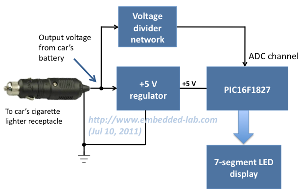
My 2010 Equinox has got every feature that a modern automobile should have. However, one thing that I personally find missing is the real-time monitoring of voltage across the car’s battery terminals. This may not seem to be that important but one of the most common reasons for a car battery failure is the faulty charging system. If the charging system is not working properly, the battery will not get the proper charging voltage (about 13.8 V for 12V battery) across its terminals and it could go flat. This project is about making a simple electronic voltage monitor system for car’s battery and its charging system. It plugs into the car’s cigarette lighter receptacle and displays the instantaneous output voltage across the battery terminals on a 4-digit seven segment LED display. This helps you to get early warnings for possible battery and its charging system problems. Microchip’s PIC16F1827 is the main controller in this project, which uses the built-in Fixed Reference Voltage (FVR) module to achieve a very precise and accurate A/D conversion of the battery voltage.

Car's battery and charging system voltage monitoring device

Read more

How to make a contact-less digital tachometer using IR-light reflection technique

Tachometer is a device that measures the rotational speed of any shaft or disc. The unit of the measurement is usually revolutions per minute or RPM. The traditional method of measuring RPM of a rotating shaft was based on velocity feedback concept where a dc generator is hooked to the rotating shaft so that the voltage induced across the generator’s terminals is proportional to the speed of the shaft. Today, we are going to make a digital tachometer based on a PIC microcontroller that requires no physical contact with the rotating shaft to measure its rotational speed. The physical contact is avoided by using an optical detection technique that requires an infrared light emitting diode in conjunction with a photo detecting diode. StartUSB for PIC from mikroElektronika is the main controller board used in this project. To read more about this board, visit my article Getting started with PIC18F Microcontrollers. This tachometer can measure speeds up to 99960 RPM with the resolution of 60 RPM. The result is shown on a 16×2 character LCD display.

Contact-less digital tachometer using StartUSB for PIC and optical sensors

Read more

A Beginner’s data logger project using PIC12F683 microcontroller

It is a very simple data logger project based on PIC12F683 microcontroller. The microcontroller reads temperature values from a temperature sensor on a regular interval basis and stores them into its internal EEPROM memory. The recorded temperatures can be later transferred to a PC through serial interface. I originally published this project on electronics-lab.com last summer. I thought this could be a very good learning project for beginners, and so I am posting it here for Embedded Lab’s readers too.

Finished temperature logger powered from a 9V battery

Read more

DIY remote controlled turret gun

Chris (@ pyroelectro.com) built his own airsoft turret gun that can rotate, tilt up and down, and fire very precisely. It is controlled through IR signals from a generic TV remote. The PIC18F4520 microcontroller is the brain of this project, which interprets the received IR signals from the TV remote and control the motion and the firing mechanism inside the gun. It is able to rotate upto 180° or more left and right, and the barrel can go up to 45° towards the sky.

Turret Gun made by Chris at pyroelectro.com

Read more

Programmable digital timer switch using a PIC Microcontroller

Digital timer switches are used to control the operation of electrical devices based on a programmed schedule. This project describes a programmable digital timer based on the PIC16F628A microcontroller that can be programmed to schedule the on and off operation of an electrical appliance. The appliance is controlled through a relay switch. This timer switch allows you to set both on and off time. That means, you can program when do you want to turn the device on and for how long you want it to be remained on. The maximum time interval that you can set for on and off operation is 99 hours and 59 minutes. The project provides an interactive user interface using a 16×2 character LCD along with 4 push buttons.

Programmable digital timer

Note: (June 30, 2016) A revised version of this project with added new features is posted here.

Circuit Design

The circuit diagram of this project is shown below. A 5V relay is driven by a PN2222 transistor that is controlled by RB3 pin of PIC16F628A. Digital inputs from the 4 push buttons are read through port pins RA2, RA3, RA4, and RB0. The functions of these push buttons are discussed in the operation section below. A standard 16×2 character LCD is used in the project to display the device status, program menu and time. The LCD is operated in 4-bit mode, therefore, only 6 I/O pins of PIC16F628A are required to drive it. A piezoelectric buzzer provides audible tone when the timer is started and stopped. It also beeps when the device is turned on or off. The + 5V power supply for the circuit is derived from a LM7805 regulator IC. The input to the regulator is given from a 9V DC wall adapter.

Read more

« Older Entries