Getting started with PIC18F Microcontrollers
|
|
After writing quite a bit of experimental tutorials on PIC16F series of microcontrollers, I thought of moving forward to the enhanced-range family of PIC microcontrollers, the PIC18F, which was introduced by Microchip in late 90s. Although PIC16F series are excellent general purpose microcontrollers, certain limitations have emerged, such as, they have limited program and data memory, their stack size is small, and all the interrupt sources have to share a single interrupt vector. Their limited instruction set also doesn’t provide direct support for more advanced peripherals interfaces like USB and CAN. The basis of the PIC18F Series is to address the issues that limit the PIC16F series. The PIC18F series of microcontrollers has larger instruction set, more memory, bigger stack, more external interrupts, higher speed, enhanced I/O port architecture, and many more features that we will be exploring in upcoming tutorials. I have decided that I am not going to spend much time on soldering and making my own prototyping board for PIC18F microcontroller as I did for PIC16F. I am going to use StartUSB for PIC board from mikroElektronika for writing these tutorials.

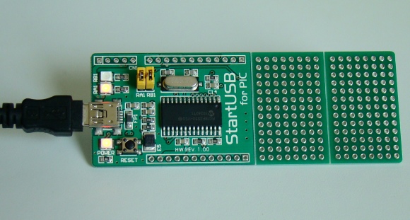
StartUSB for PIC board from mikroElektronika
So what is StartUSB for PIC?
StartUSB for PIC is a small development board featuring PIC18F2550 microcontroller with fast USB 2.0 support. It features connection pads for all MCU pins, as well as two additional prototyping areas for placing additional components. The biggest advantage of this board is that the microcontroller comes preprogrammed with fast USB bootloader, and so there is no need of any external programmer. You can transfer your application related HEX file from PC to PIC’s program memory using mikroBootloader. MikroBootloader is the PC application developed by mikroElektronika for their USB HID Bootloader. On board miniUSB connector, oscillator (8.0 MHz crystal), reset circuit, power indicator LED, as well as two additional LEDs provide all you need for quick start. The two additional LEDs are connected to RA1 and RB1 pins of PIC18F2550 through jumpers. The picture above shows the StartUSB for PIC board with all the components and additional prototyping areas.
Today’s tutorial is important because we will discuss about a complete setup for StartUSB for PIC board that will let you start your journey into the world of PIC18F series microcontrollers. The first thing you need to install is mikroC Pro for PIC, which is a C compiler developed by mikroElektronika for PIC12, PIC16, and PIC18 series microcontrollers. You can download the demo version of this software that will allow you to compile programs up to 2 K of program words. Once you installed the compiler, download the mikroBootloader, which is PC’s application to communicate with the bootloader program stored inside the PIC18F2550 microcontroller on the StartUSB board. The user’s guides for StartUSB for PIC and mikrobootloader can be downloaded from the following links.
The user’s manual for StartUSB board provides the circuit diagram of the board and instructions on how to connect it to PC for downloading the application HEX file using mikroBootloader. Please read these details in the manuals before proceeding forward.

Circuit diagram of StartUSB for PIC board with two LEDs connected to RA1 and RB1
Testing the board with “Hello World”
We will begin our journey with a simple test program that will make sure everything is setup correctly and we will be ready for doing more advanced experiments with PIC18F2550. This program will flash the two on-board LEDs (connected to RA1 and RB1 pins) alternately with 500 ms duration. In mikroC Pro for PIC, applications are developed in the form of projects. If you haven’t used mikroC Pro for PIC before, the document ‘Creating first project in mikroC Pro for PIC‘ from mikroElektronika will guide you to create your first project. While following those steps, select the microcontroller as PIC18F2550 and the device clock as 8.0 MHz. In the main program window, type in the following program.
Build the program to get the HEX file and then load it into the PIC18F2550 microcontroller using mikroBootloader application. Follow the instructions mentioned in the user’s manual for StartUSB board for this. Once the program is loaded, reset the board and wait for 5 sec till the microcontroller comes out of bootloader mode and starts executing the newly loaded application. You will see the two on-board LEDs flashing alternately. Wait a minute, they were programmed to flash with 0.5 sec duration but you will see they are doing much faster than that. It seems like the microcontroller clock is much faster than the applied external oscillator (8.0 MHz). This is possible in PIC18F2550 because of the presence of built-in PLL circuitry.

Flashing LEDs on StartUSB for PIC board
The USB module on-board PIC18F2550 requires 48.0 MHz clock for its full speed operation. This clock is derived from the built-in 96 MHz PLL module by dividing its output by 2. The PLL itself is driven by a 4 MHz input signal derived from the primary clock source, which is 8.0 MHz crystal in our case. The required 4.0 MHz for driving the PLL can be, therefore, obtained from the 8.0 MHz source by using the PLL Prescaler value of 2. The output from PLL (96 MHz) is then divided by 2 to get 48 MHz clock required for USB operation. The microcontroller core and other peripherals can also use this clock speed but not necessarily. There are other options to achieve the USB module clock requirement and still provide flexibility for clocking the rest of the device from the primary oscillator source. These details are found in the datasheet of PIC18F2550. But, in case of StartUSB for PIC board, due to the requirement of USB bootloader, the USB module and the microcontroller core, both uses 48.0 MHz clock derived from PLL. Unfortunately, the bootloader program does not allow the user to change the clock setting, and therefore, it is always 48.0 MHz, unless you erase the bootloader first and then use an external programmer to modify the configuration registers for clock setting. So, the on-board PIC18F2550 microcontroller is actually running at 48.0 MHz, and not at 8.0 MHz. That’s why the LEDs are flashing much faster. In order to correct for this, open the Edit Project window from the Project menu in mikroC, and make sure the clock settings match with what is shown below.

Proper clock settings for StartUSB for PIC board
Next, save the project, build it again, and reload the HEX file into PIC18F2550. Now, you will see the LEDs are flashing at correct rate. So, you are all setup for your journey with PIC18F microcontrollers. Stay tuned for more advanced experimental tutorials on PIC18F.
|
|
Pingback: Modulo PICnano con PIC18F2550 compatible con Arduino Nano
Pingback: PICnano module with PIC18F2550 and compatible with Arduino Nano
good work
dear thanks very much for this info, i spend two week for test uat for this card,but with ur help it’s finshed with about 20 mintus.
how can I buy this?
Pingback: Humidity and temperature measurements with Sensirion’s SHT1x/SHT7x sensors | WORLD OF ELECTRO
I just was wondering how much memory does the bootloader occupy?
Today I was able to read the device with PicKit2, I found that the bootloader occupies memory from line 10079 to 13435. That equals to 3359 lines. I was using MPLAB v8.66.
Andrius,
I was also wondering about that. I am gonna ask mikroE people and see what they say. Actually, I have been quite busy since past two weeks, so could not get time for doing projects with StartUSB. I will let you know once I have any update. Thanks.
Received mine today. Evertyhing works. Can’t wait for some new projects and modifications for this board.
For PIC programming, development and most importantly, simulation for debugging, I’ve yet to find a better tool than Oshonsoft PIC Simulator. The PIC18 Simulator even comes with USB support and creates USB HID devices in less than a dozen lines of code!
Oshonsoft website here
Excellent intro! We can’t wait to read more!
Hi,
Very nice one, would like to buy one.
Are they orderable in India?
Very nice intro. Ordered mine StartUsb today. As soon as I get it I will test it with this program. Can’t wait to see what other projects will You offer us 🙂 Keep up the good job.
Pingback: Electronics-Lab.com Blog » Blog Archive » StartUSB for PIC board