Product review: iCP12 usbStick and SmartDAQ
In this blog post, I am reviewing iCircuit Technologies’ iCP12 usbStick development board and their freely downloadable SmartDAQ PC software. These two can be bundled together to construct a very basic 6-channel (analog) PC data logger.
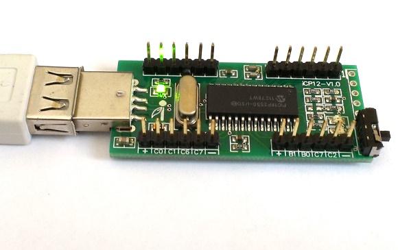
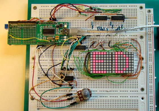
iCP12: PIC18F2550 USB board
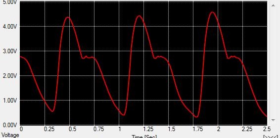
The iCP12 usbStick is a PIC18F2550 based USB development board that comes preloaded with Microchip’s USB HID bootloader that allows users to upload an application firmware directly through a PC’s USB port without any external programmer. It provides access to its I/O pins through 0.1″ pitch headers. A slide switch is also provided on board to select the operation of the board in Bootloader or Normal mode. The iCP12 usbStick board is shipped with a preloaded data acquisition firmware (HEX file is also downloadable) that emulates as a virtual COM port to PC. Thereafter, the communication between the PC and usbStick is serial. The firmware also supports basic I/O control and data logging feature. They provide a PC application named SmartDAQ that is specially developed to communicate with the usbStick (data acquisition firmware must be loaded) and control its I/O pins, PWM outputs, and record ADC inputs. Read more