Lab 12: Basics of LED dot matrix display
|
|
We covered how to interface seven segment LED displays to a PIC microcontroller in two sections: Lab 6 and Lab 11. Today, we will move on to interfacing an LED dot matrix display. LED dot matrices are very popular means of displaying information as it allows both static and animated text and images. Perhaps, you have encountered them at gas stations displaying the gas prices, or in the public places and alongside highways, displaying advertisements on large dot matrix panels. In this experiment, we will discuss about the basic structure of a monochrome (single color) LED dot matrix and its interface with a microcontroller to display static characters and symbols. We will cover the animation stuff in next tutorial. I am using the PIC18F2550 microcontroller on the StartUSB for PIC board for demonstration, but this technique is applicable to any other microcontrollers that have sufficient I/O pins to drive the LED matrix.

Interfacing a LED dot matrix display with a PIC microcontroller
Theory of LED dot matrix display
In a dot matrix display, multiple LEDs are wired together in rows and columns. This is done to minimize the number of pins required to drive them. For example, a 8×8 matrix of LEDs (shown below) would need 64 I/O pins, one for each LED pixel. By wiring all the anodes together in rows (R1 through R8), and cathodes in columns (C1 through C8), the required number of I/O pins is reduced to 16. Each LED is addressed by its row and column number. In the figure below, if R4 is pulled high and C3 is pulled low, the LED in fourth row and third column will be turned on. Characters can be displayed by fast scanning of either rows or columns. This tutorial will discuss the method of column scanning.

Structure of a 8x8 LED dot matrix
The LED matrix used in this experiment is of size 5×7. We will learn how to display still characters in a standard 5×7 pixel format. The figure below shows which LEDs are to be turned on to display the English alphabet ‘A’. The 7 rows and 5 columns are controlled through the microcontroller pins. Now, lets see in detail how it works.
Suppose, we want to display the alphabet A. We will first select the column C1 (which means C1 is pulled low in this case), and deselect other columns by blocking their ground paths (one way of doing that is by pulling C2 through C5 pins to logic high). Now, the first column is active, and you need to turn on the LEDs in the rows R2 through R7 of this column, which can be done by applying forward bias voltages to these rows. Next, select the column C2 (and deselect all other columns), and apply forward bias to R1 and R5, and so on. Therefore, by scanning across the column quickly (> 100 times per second), and turning on the respective LEDs in each row of that column, the persistence of vision comes in to play, and we perceive the display image as still.

A standard 5x7 LED dot matrix display structure
The table below gives the logic levels to be applied to R1 through R7 for each of the columns in order to display the alphabet ‘A’.

Row values of each column for displaying the alphabet A

Scanning across the columns and feeding with appropriate row values
You should have noted that across each row, one pin is sourcing the current for only one LED at a time, but a column pin may have to sink the currents from more than one LED. For example, the column C1 should be able to sink the currents from 6 LEDs while displaying the alphabet ‘A’. A microcontroller’s I/O pin cannot sink this much of current, so external transistor arrays are required. I am using ULN2003A IC which has seven built-in Darlington transistor arrays (see below). The inputs of ULN2003A are active high. This means the input pins must be supplied with logic high in order to bring the corresponding output pins to ground. The schematic of the Darlington transistor array inside the ULN2003A chip is shown below.

Pin diagram and schematic of ULN2003A (Darlington transistor arrays)
Circuit Setup
The circuit setup for this experiment is quite simple. You need seven 330 ? resistors in series with rows R1 through R7 to limit the current through the LEDs. Then the rows are driven by RB0 through RB6 pins of PIC18F2550. The columns are connected to the five outputs of ULN2003A. The corresponding five input pins of ULN2003A IC are controlled by RA0 through RA4 pins of PIC18F2550. The microcontroller will, therefore, scan across the column by sending appropriate bits to PORTA. For example, setting RA0 to 1 and clearing RA1 through RA4 bits, will select the first column. The microcontroller will wait for about 1 ms before switching to the next column. At each column, the microcontroller will output the corresponding row value at PORTB to turn on the appropriate LEDs in the column that are required to display the specific character. The switching between columns is fast enough to deceive the human eyes and a steady character is displayed.

Circuit diagram for interfacing a 5x7 LED dot matrix with PIC18F2550

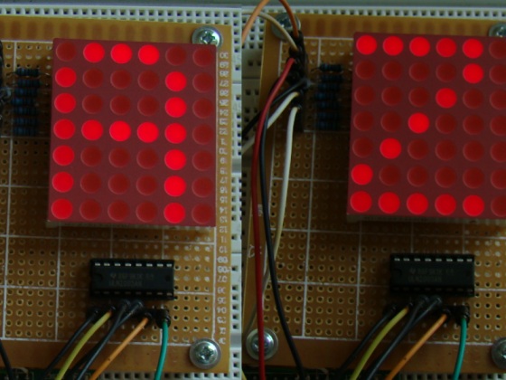
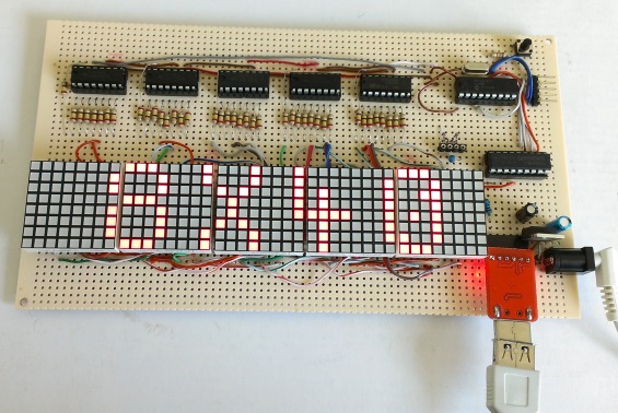
Circuit setup showing a StartUSB board with a 6x7 LED dot matrix (the sixth column is discarded here)
Software
The major part of this experiment is the software routine to scan the columns and feed the rows with appropriate values. The column-specific row values for display characters can be either defined in RAM or stored in the program memory in case the on-board RAM is not sufficient enough. In mikroC, the variables are saved in RAM and constants are stored in program memory. So, if your PIC does not have enough RAM, you can define a constant array to store the row values so that a part of the program memory is occupied by it to free up the on-board RAM. PIC18F2550 has quite a bit of RAM (2 KB), so I have used RAM to store the row values for alphabets A through Z. Here’s how I define it in mikroC,
And this is how mikroC allows you to store arrays in the program memory.
const unsigned short characters[30]={
0x24, 0x2A, 0x7f, 0x2A, 0x12, // $
0x08, 0x14, 0x22, 0x41, 0x00, // <
0x41, 0x22, 0x14, 0x08, 0x00, // >
0x14, 0x14, 0x14, 0x14, 0x14, // =
0x36, 0x49, 0x55, 0x22, 0x50, // &
0x44, 0x3c, 0x04, 0x7c, 0x44, // PI
};
I have written a simple program in mikroC to display the alphabets A through Z sequentially, and some special characters too. You can watch the video below to see how they look like on the dot matrix display.

Displaying symbol PI
|
|
Good day to you all please let’s create a WhatsApp group my phone number is +2347035557795
Plz my dot matric is 8×8 and it small when it display plz how can I do it so dat it can be thick.
Sir can i have toput solenoides instead of led bulbs on dot matrix board, to switch on an individual solenoides, or how to prepare dot matrix board to switch on an only required solenoides pls give info
Hello Sir, I am trying to configure your above code with PIC16F877A and MPLABX HitechC compiler. Sir I am getting an error could not find space (260 bytes) for variable _Alphabets while compiling the code. can you please help me with this error ? Thanks.
Ok sir I got it I need read all of your details completely, so found my mistake of low RAM space, after placing constant arrray I got my error problem solved. Thank you sir.
Hi,
Curious about the purpose of the ULN2003, hoping someone could clarify this. I have a 4×4 matrix of LEDs that require 20mA to get them to full brightness. The microcontroller drives the rows. My micro is limited to 10mA output drive. If I drive the signal HIGH from the micro to enable a particular LED, let’s say R1, and then drive the ULN2003A pin to to sink current from column 1 which would then light up R1-C1 LED, wouldn’t the source of the current still be from the micro’s drive on the row R1?
If so, what’s the point of using a device that can sink 500mA when most micro’s are not capable of much more than 10mA drive? Or am I missing something?
What would be used in the ROW drive if more current was required, just a buffer?
Thanks…
Each output pin of ULN2003 will sink the sum of currents from all the LEDs that are ON in a column. Each microcontroller pin will drive one LED at a time but multiple LEDs can be ON in a column; that’s why we need a column driver with a higher current capacity.
OK, thanks for the reply!
I understand what you are saying, but I think this would only be true if you were scanning. If I wanted to have all LEDs in R1 ON, (one row sourcing, all 8 columns sinking) that would require more drive current than is available from my controller, isn’t that correct? I have cases where I need to drive all LED’s at once, or almost all LED’s. My application is not a matrix, but LEDs on a tactile keyboard that are connected like a matrix.
In any case, I have built a prototype using a MIC2981 high side driver between the controller outputs on the rows and the LED anodes. It works well and the cost of the device is relatively inexpensive compared to stressing the controller.
I also meant to add that I am using the ULN2003 along with the MIC2981, thanks!
Pingback: LED Matrices | Joe's Electronics Adventures
Any brother help me.how to make pov display by 8 LEDs? Show name
The LED matrix used in this project is 6 by 7. This code does not work of 5 by 7 LED matrix, please fix it.
I try to simulate this circuit before using real components by Proteus ISIS. But somehow i got some problems.
1- As Paul said mikroC files written due to 6×7 dot matrix display
I try to fix this (because i am using 5×7 dot matrix model) changing those statements :
for (repeat=0; repeat<100; repeat++){
column = 1;
for(count = num*5;count < (num*5+5);count++){
PORTB = Alphabets[count];
PORTA = column;
column = column<<1;
2- Everything was going good while i was debugging in mikroC. Step by step I watched all the values were accurate.When i ran the simulation there was a problem. 1st column till 4th column everything was fine. The 4th column illuminating the dots (due to hex code) then extinguishes after fully illuminates less then a second (0x7F for every letter). I extended the delay time to understand what is going on but this 4th. column flashing time didn't change. The 5th column is working good. Then I thought maybe this flashing issue about Proteus response time. I change the 5×7 dot matrix display response time 10ns. but i got the same result. Maybe i miss smthng. else… Is there anybody who simulate this circuit by Proteus (ISIS)?
I fix the problem now everything is working fine (Proteus ISIS simulation). The problem is not about 5×7 dot matrix response time. It is about one missing sentence. User should zeroize Port A. And code is working fine with 5×7 dot matrix. Thank you.
for (repeat=0; repeat<100; repeat++){
column = 1;
for(count = num*5;count < (num*5+5);count++){
PORTA = 0; ———————————————————————+++++ missing sentence ++++ !!!!!
PORTB = Alphabets[count];
PORTA = column;
column = column<<1;
Hello,
I use for driving my led matrix displays driver MAX 7219, its very simply – here is the result:
https://www.youtube.com/watch?v=6qpGJTIwv_M
I can’t understand this instruction line.
column=1;
According to my thought,
When PORTA = column;
Then PORTA = 1; (Value of column is defined 1 somewherein prog)
Then all the pin of PORTA will be high. I mean, RA0 thorough RA4 will be high. And this will active all connected pin of UNL2003. In other manning, it will active all the column. So it’s not according to our demand.
But, if we apply the o/p of PORTA directly to columns then the program is okay (but will face prob to sink current of all columns).
i have need more c program and assembly language program
please post circuit diagram
sir, plz help me.
Sir, i would like to know more about dot matrix display . How can send data to the display ..?
In the Theory of LED dot matrix display says “For example, a 8×8 matrix of LEDs (shown below) would need 64 I/O pins, one for each LED pixel”. Is not the number of I/O that should be required is 65 (because it takes 1 extra I/O as the common) ? Please the explanation, thank you ..
can you help do a project liker the one you done that, but my project want more word as such as: welcome to souphanouvonguniversity ………& each other). i will play you money
u are always provide code for rows but can u please provide the code for columns . i mean can we connect columns to controller or any other device or there is any software for that……………………..
and also kindly please explain about how to connect and write the program of two or more than 2 led dot matrix
thanking you sir,
Sir,
I have a PIC32MX320F128H, a led matrix 7×5 and ICs 74HC595, but i dont know how to make connections in the breadboad. Could you give me the schematic?
Thank you
ULN2003 and ULN2803
What is the diffrence betweenCD4082 and CD4081 ?
What is the diffrence between ULN2003 and ULN2803 ?
thank you!
marC:)
can you please explain in few words how you converted the above digits corresponding to different rows,because where you said:
unsigned short Alphabets[130]={ 0x7e, 0×09, 0×09, 0×09, 0x7e, // I am not getting how you get those values ;on my behalf when I convert I am getting: {0x7F,0X88,….}
Please help on this conversion.
Thanks
these are individual BCD codes converted to hexadecimal codes.
ex: 0x7e means,
0b01111110
______________
7= 0111
3=1110, whereas 0x / 0b are syntax for writing hex ob bin code.
Pingback: Dot Matrix Display by principle of Persistence of Vision using STM32F100RB | DIYSection
thank u so much for urs info..
Its very interesting but how can how to I add more LED dot matrix and how does C code changes generally. I am a beginner in Microcontroller.
thx for this project
please can you help me with the isis shematic of lab 12 and the christmas messsage because they dont work with me and i dont know the problem
Sir.Please me ,full details of Dot-matrix,construction.
Could you share me how a real time message to be display on the dot matrix. please share some techniques on how to do it. Please help me how to decode a web message and put it into the dot matrix display. thanks ahead.
sir please sir help me with circuit diagram,codes and component needed for the construction of led dot matrix display with atleast 150 LED, which will be displaying DEPARTMENT OF ELECTRICAL/ELECTRONIC ENGINEERING IMT ENUGU CAMPUS BY GROUP 2.
Hello sir,am given project on moving message display using bicolor LED.pls help me with circuit diagram and how to connect them.as sson as possible.
Sir,
Our project is to make a clock using 4 dot matix,89C51 & decoder .how can I do this by using assembly language.I need the solution(code & circuit diagram) before April 25th.
Sir,
Our project is to make a clock using 4 dot matix,89C51 & decoder .how can I do this by using assembly language.I need the solution(code & circuit diagram) as soon as possible.
if there are more columns in dot matrix led display how i can interface these columns with micro controller ports,as pins of micro controller are limited in number
Use shift registers (e.g. 74HC595) or other I/O expanders (such as MCP23008). See this: http://embedded-lab.com/blog/?p=2661
Pingback: Proteus problem on displaying letters for Dot Matrix Display
Dear Sir,
I want 10 such led displays to be mounted in one line. what changes will i have to make in the software and the hardware. Please help.
Thanking you,
Regards,
Naren
Superb!
Pingback: .NET i jiné ... : Odkazy z prohlíže?e - 24.6.2011
Is there a reason why you swap the Rows and Column headings in your chart ‘Row values for displaying the alphabet A’?
It took a second to figure out why it didn’t match up with the scanning columns which followed. Sure its not that difficult to translate once you figure out what’s going on, but why make it more difficult for the reader.
I think it would make for an easier read if you chart orientation was the same as the rest of the posting. That is, with Rows going from top to bottom and Columns from left to right.
Otherwise, a nice article.
Thanks,
– Bill
Hey Bill,
I realized what you said, and I have modified the table accordingly. Thanks.
Pingback: led display « Conan Orona's Journal Technia
Pingback: A beginner’s guide to LED matrices - machine quotidienne
Pingback: A beginner’s guide to LED matrices - Hack a Day