PIC Tutorials: Experimenting with PIC Microcontrollers
One of the most popular and easy to use microcontroller families available in the market today is the Microchip “PIC microcontroller”. The following experimental PIC tutorials are intended to facilitate the learning of PIC microcontroller interfacing and programming. Each topic is started with the background theory followed by simple experiments to explain how the theory can be implemented into actual applications. I am emphasizing the use of high level language (C) for PIC programming. The C compiler used in writing the programs is mikroC Pro for PIC from MikroElektronika. You can download and install the demo version of this compiler that limits the size of the output HEX file to 2K. PIC16F688 and PIC16F628A microcontrollers are chosen for the most basic experiments whereas the advanced topics are discussed with PIC18F2550. I hope some of you will find these tutorials helpful for coming up to speed on PIC microcontrollers. If you have any suggestions or comments, you can email me at [admin (at) embedded-lab.com].
Pre-Lab PreparationWhat is an Embedded System? Hardware and Software requirements Choosing a PIC Programmer Regulated power supply for your breadboardGetting ready for the first lab Breadboard module for PIC16F688 Breadboard module for PIC16F628A |
|
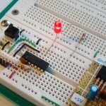
Lab 1: Flashing an LEDStart with the “Hello World” project to make sure that every set up you have made is correct and working well. You will use a PIC16F688 microcontroller to flash an LED on and off. Required Theory : I/O ports in PIC16F688 |
|
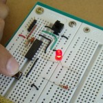
Lab 2: Basic digital input and outputLearn how to read digital inputs from a push button switch. Every time the push button is pressed, the LED will be toggled on and off. You will also learn about the bouncing characteristic of a switch, and how to take care of that. Required Theory : I/O ports in PIC16F688 |
|
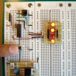 |
Lab 3: Four bit binary counterFour LEDs are connected to a PIC16F688 microcontroller to make a 4-bit binary counter. The counter counts the pressing of a push button. It starts from 0 and is incremented on every press. When it reaches 15, it overflows and the next output will be o again. Required Theory : I/O ports in PIC16F688 |
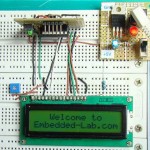 |
Lab 4: Interfacing a character LCDHD44780 based LCD displays are very popular among hobbyists because they are cheap and they can display characters. Besides they are very easy to interface with microcontrollers and most of the present day high-level compilers have in-built library routines for them. Learn how to include one in your microcontroller project. Required Theory : Provided in the article |
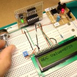 |
Lab 5: Analog-to-digital conversion (ADC)Analog-to-digital conversion (ADC) is necessary because, while embedded systems deal with digital values, their surroundings typically involve many analog signals such as, temperature, speed, pressure, etc. Learn how to interface analog signals with a PIC microcontroller. Required Theory : ADC channels in PIC16F688 |
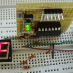 |
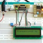
Lab 6: Interfacing a seven segment displaySeven segment LEDs are mostly used to display decimal numbers. They are popular because they are visually attractive and easy to interface. This lab session discusses about the functioning of seven segment display modules and driving a single module with a PIC microcontroller to display numbers. Required Theory : Provided in the article |
 |
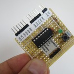
Lab 7: Timers and Counters (Part 1)Hardware timer modules are used in microcontroller based systems for accurate event timing and counting. This experimental tutorial describes the Timer0 module in PIC microcontrollers and it’s functionality. Two programs are written to demonstrate the timer and counter functions separately. Required Theory : Provided in the article |
Pingback: Electronics-Lab.com Blog » Blog Archive » Experimenting with PIC Micro