Tag Archives: PIC16F1827


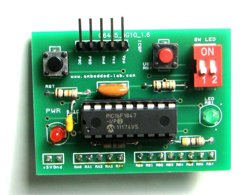
Breadboard module for 18-pin PIC16F microcontrollers (PCB version)

Because of their compact size, ease of use and many built-in peripherals, the 18-pin PIC16F series processors (PIC16F628A, PIC16F88, and now PIC16F1827/47) have always been my favorite microcontrollers. Many of my projects and tutorials written in this blog also use PIC16F628A and PIC16F1827 microcontrollers. As I will be using them more in the future too, I thought of making some PCB versions of my breadboard module for PIC16F628A with some modifications. I used Iteadstudio’s PCB prototyping service for this, and I would say the PCBs turned out really well for the price I paid. I used their 2 layer 5cm x 5cm service and got 10 PCBs for less than $15, including shipping to the United States.

Mini breadboard module for 18-pin PIC microcontrollers

Read more

Lab 18: Matrix keypad interfacing

Matrix keypads are very common input devices in embedded systems. They have simple architecture and are easy to interface. One good thing about them is that they allow you to interface a large number of input keys to a microcontroller with minimum usage of  I/O resources. This tutorial describes two different approaches of reading input data from a 4×4 (16 keys) matrix keypad interfaced to a PIC microcontroller. The pressed key information is displayed on a character LCD. The microcontroller used in this experiment is PIC16F1827.

4x4 matrix keypad interfaced to PICMicro

Read more

Voltage monitor for car’s battery and its charging system

My 2010 Equinox has got every feature that a modern automobile should have. However, one thing that I personally find missing is the real-time monitoring of voltage across the car’s battery terminals. This may not seem to be that important but one of the most common reasons for a car battery failure is the faulty charging system. If the charging system is not working properly, the battery will not get the proper charging voltage (about 13.8 V for 12V battery) across its terminals and it could go flat. This project is about making a simple electronic voltage monitor system for car’s battery and its charging system. It plugs into the car’s cigarette lighter receptacle and displays the instantaneous output voltage across the battery terminals on a 4-digit seven segment LED display. This helps you to get early warnings for possible battery and its charging system problems. Microchip’s PIC16F1827 is the main controller in this project, which uses the built-in Fixed Reference Voltage (FVR) module to achieve a very precise and accurate A/D conversion of the battery voltage.

Car's battery and charging system voltage monitoring device

Read more

Using Fixed Voltage Reference (FVR) for A/D conversion in enhanced mid-range PIC microcontrollers

The reference voltage plays a very important role in any A/D conversion. It determines both the range and the resolution (Volt/Count) of the A/D conversion. Besides, the accuracy of the conversion also depends upon how stable the reference voltage is. Usually in PIC microcontrollers, the reference voltage for A/D conversion can be selected as the supply voltage itself or provided externally through one or more I/O pins. But the new enhanced mid-range family of 8-bit PIC microcontrollers have a built-in module that generates a stable reference voltage internally. It is called Fixed Voltage Reference (FVR) where the output is very stable and independent of the supply voltage (VDD). The output of the FVR can be configured to supply a reference voltage for A/D conversion internally. This article describes how to configure the FVR module to derive the reference voltage of 2.048 V for A/D conversion in PIC16F1827 microcontroller. The analog signal for this experiment is taken from the output of a LM34DZ temperature sensor. After the A/D conversion, the PIC16F1827 displays the temperature on a 2×8 character LCD.

Using internal FVR for A/D conversion of LM34 analog output

Read more

How to interface MAXIM’s DS1868 digital potentiometer with a PIC microcontroller

Potentiometers find applications in many electrical devices. For example, a light dimmer uses a potentiometer to control the brightness of lamps. In amplifiers, they are used to control the output volume of the music, or change the bass level. In an adjustable power supply we see potentiometers to vary the output voltage and current. In a frequency generator, they are used to control the duty cycle and frequency of the output signal. These potentiometers are electro-mechanical transducers that convert the rotary or linear displacement into a change in resistance. This change in resistance can be used to control anything from the brightness of a lamp to the direction of a rocket. But things have been changed lately. You can now vary the brightness of the lamp with touch switches. The volume of an amplifier can be controlled through a remote, and the frequency of an oscillator can be varied with tact switches. There are still potentiometers in these devices but in the form of silicon chips and not in the conventional electro-mechanical form. These are called digital potentiometers and today we will discuss about MAXIM’s DS1868 chip, which has two digitally controlled potentiometers. We will interface it to a PIC16F1827 microcontroller and vary the position of the wiper terminals from one end to the other.

Controlling the wiper position of DS1868 digital potentiometer

Read more

« Older Entries