Tag Archives: pic16f628a


Heart rate measurement from fingertip

Introduction

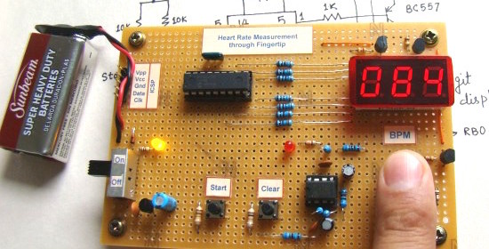
Heart rate measurement indicates the soundness of the human cardiovascular system. This project demonstrates a technique to measure the heart rate by sensing the variation of the blood volume inside a finger artery, which is caused by the pumping action of the heart. It consists of an infrared LED that transmits an IR signal through the fingertip of the subject.  A part of this infrared light is reflected by the blood cells. The reflected signal is detected by a photo diode sensor. The changing blood volume with heartbeat results in a train of pulses at the output of the photo diode, the magnitude of which is too small to be detected directly by a microcontroller. Therefore, a two-stage, high gain, active low pass filter is designed using two Operational Amplifiers (OpAmps) to filter and amplify the signal to appropriate voltage level so that the pulses can be counted by a microcontroller. The heart rate is displayed on a 3 digit seven segment LED display. The microcontroller used in this project is PIC16F628A.

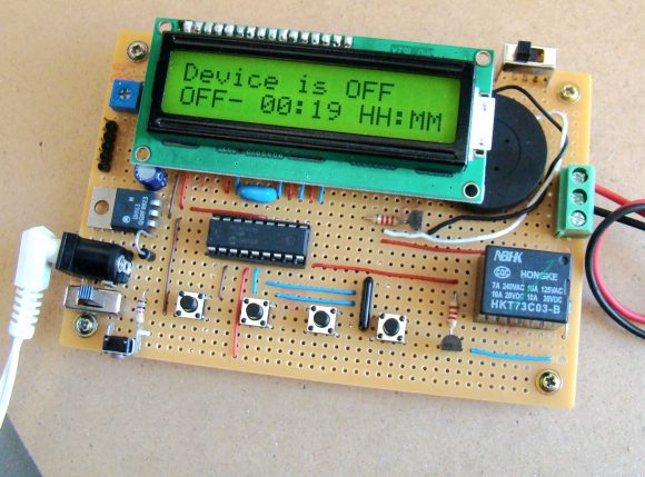
Heart rate measuring device using PIC16F628A

Read more

Programmable digital timer switch using a PIC Microcontroller

Digital timer switches are used to control the operation of electrical devices based on a programmed schedule. This project describes a programmable digital timer based on the PIC16F628A microcontroller that can be programmed to schedule the on and off operation of an electrical appliance. The appliance is controlled through a relay switch. This timer switch allows you to set both on and off time. That means, you can program when do you want to turn the device on and for how long you want it to be remained on. The maximum time interval that you can set for on and off operation is 99 hours and 59 minutes. The project provides an interactive user interface using a 16×2 character LCD along with 4 push buttons.

Programmable digital timer

Note: (June 30, 2016) A revised version of this project with added new features is posted here.

Circuit Design

The circuit diagram of this project is shown below. A 5V relay is driven by a PN2222 transistor that is controlled by RB3 pin of PIC16F628A. Digital inputs from the 4 push buttons are read through port pins RA2, RA3, RA4, and RB0. The functions of these push buttons are discussed in the operation section below. A standard 16×2 character LCD is used in the project to display the device status, program menu and time. The LCD is operated in 4-bit mode, therefore, only 6 I/O pins of PIC16F628A are required to drive it. A piezoelectric buzzer provides audible tone when the timer is started and stopped. It also beeps when the device is turned on or off. The + 5V power supply for the circuit is derived from a LM7805 regulator IC. The input to the regulator is given from a 9V DC wall adapter.

Read more

Lab 9: Pulse Width Modulation (PWM) using PIC CCP module

Description

Pulse width modulation (PWM) is a technique of controlling the amount of power delivered to an electronic load using an on-off digital signal. The fraction of the period for which the signal is on is known as the duty cycle. The average DC value of the signal can be varied by varying the duty cycle. The duty cycle can be anywhere between 0 (signal is always off) to 1 (signal is constantly on). Suppose, if the signal has +5 V while it is on and 0 V during off condition, then by changing the duty cycle of the signal, any voltage between 0-5 V can be simulated. This method is commonly used for controlling speeds of DC motors and brightness of lamps. This lab session will talk about how to generate a PWM signal using the PIC16F628A microcontroller and control the brightness of an LED with it. PIC16F628A has a built-in hardware, called Capture/Compare/PWM (CCP) module, to generate a PWM signal.

Read more

Breadboard module for PIC16F628A

Here’s another breadboard module that carries a PIC16F628A microcontroller. The power supply pins and the I/O ports of the PIC16F628A microcontroller are accessed through male headers. It can be easily plugged into a breadboard and is very useful for quick prototyping. It frees up a lot of space on the breadboard since the oscillator, reset, and ICSP circuits are already built on the module. It is different from the previous PIC16F688 breadboard module in the way that the microcontroller now runs with an external 4.0 MHz crystal. So, this module will be more appropriate for experiments that require accurate timing calculations. Besides, the PIC16F628a microcontroller allows you to read/write 8-bit data directly through PORTB, which is 8-bit wide (none of the ports in PIC16F688 were 8-bit wide).

The layout and the circuit diagram of the module is shown below. The module has ICSP header pins for in-circuit programming, a reset switch, and an LED as power-on indicator. It provides easy access to all the pins of PORTB, and RA0 through RA4 pins of PORTA. Pins RA6 and RA7 are used for external crystal connections, whereas RA5 is input only pin and is used for reset circuit.

Component layout

Read more

Single button code entry for a digital lock

Yes, it has got just one push button to enter the code to unlock the system. The author demonstrates how you can just enter multiple code numbers in sequence from a single button input. If the code entered matches with the preset pass code, a relay is turned on.

This project uses a PIC16F628A microcontroller that monitors the user inputs from the single button. You can enter a number 3 by pressing the button 3 times. Every time you enter a number, the microcontroller acknowledges by lighting an LED. When you entered all the code numbers correctly in sequence, the relay is turned on. You can connect this system to your garage door opener, or to any other security lock. The another interesting part of this project is that you can even change the pass code with the same button. For more details, visit the author’s page down below.

Read more

Recent Entries »