Humidity and temperature measurements with Sensirion’s SHT1x/SHT7x sensors (Part 1)
|
|
Temperature and relative humidity are two very important ambient parameters that are directly related to human comfort. Sometimes, you may be able to bear higher temperatures, if there is a lower relative humidity, such as in hot and dry desert-like environment. However, being in a humid place with not very high temperature may make you feel like melting. This is because if there is high relative humidity, sweat from our body will evaporate less into the air and we feel much hotter than the actual temperature. Humidifiers and dehumidifiers help to keep indoor humidity at a comfortable level. Today we will discuss about Sensirion’s SHT series of digital sensors, more specifically SHT11 and SHT75, which are capable of measuring both temperature and relative humidity and provide fully calibrated digital outputs. We will interface both the sensors to PIC18F2550 microcontroller and compare the two sets of measurements to see the consistency between the two sensors. This tutorial is divided into two parts. The first part will cover all the details regarding the sensors, including their specification, interface, and communication protocol. The second part will be more focussed on the circuit diagram, implementation of the communication protocol with PICMicro, and the results.

Relative humidity and temperature measurements with SHT1x and SHT7x sensors
Theory
Sensirion offers multiple SHT series of digital sensors for measuring both relative humidity and temperature. The temperature is measured using a band-gap sensor, whereas the humidity sensor is capacitive; which means the presence of moisture in air changes the dielectric constant of the material in between the two plates of a parallel-plate capacitor, and hence varies the capacitance. The required signal conditioning, analog-to-digital conversion, and digital interface circuitries are all integrated onto the sensor chip. The various SHT series sensors have different levels of accuracy for humidity and temperature measurements, as described below.

SHT1x, 2x, and 7x series of humidity sensors (Source: http://www.sensirion.com)
SHT1x are available in surface mount type whereas SHT7x are supplied with four pins which allows easy connection. The SHT11 and SHT75 sensors both provide fully calibrated digital outputs that can be read through a two-wire (SDA for data and SCK for clock) serial interface which looks like I2C but actually it is not compatible with I2C. An external pull-up resistor is required to pull the signal high on the SDA line. However, the SCK line could be driven without any pull-up resistor. The signaling detail of the serial bus is described in the datasheet, which we will implement for PIC18F2550 microcontroller using mikroC pro for PIC compiler. The operating range of both the sensors is 0 to 100% for relative humidity, and -40.0 to 123.8 °C for temperature. The sensor consumes 3 mW power during measurement, and 5 ?W, while in sleep mode.
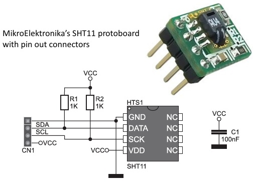
The SHT11 module that I have got is from mikroElektronika. The sensor (SMD) is soldered on a tiny proto board with all the four pins accessible through a standard 0.1 inch spacing male header. The board comes with pull-up resistors connected to both SDA and SCK lines. One concern in this type of arrangement is the heat dissipated by the pull-up resistors could affect the measurements if the resistors and the sensor are close in the board. We will discuss about this issue later too. The SHT75 module from Sensirion, however, does not include any pull-up resistor for SDA line and therefore must be included externally.

SHT11 proto board from mikroElektronika comes with pull-up resistors for both SDA and SCK lines

Pin descriptions of SHT75
Brief description of SHT1x/7x sensors
Please read the datasheets for SHT1x and SHT7x for detail information about these sensors. I am only providing a brief summary here.
SHT11 and SHT75 are functionally same with SHT75 being more accurate (±1.8% vs ±3%) in measuring relative humidity. Both the sensors can operate from 2.4-5.5 V supply voltage, however the datasheet recommends to use 3.3V for highest accuracy. The default measurement resolution is 14-bit for temperature and 12-bit for relative humidity, which can be reduced to 12- and 8-bit respectively by changing the bit settings of the Status Register (discussed later) inside the sensor chip. We will be using the default resolution settings for measurements.
SCK is the clock line that is used to synchronize the communication between the micrcontroller and the sensor. It is an input only pin on the sensor’s side and therefore the microcontroller should be responsible to generate the clock signal. DATA or SDA is a bidirectional data transfer pin for sending data in and out of the sensor. The sensor should receive a conversion command from the microcontroller in order to start measuring temperature or relative humidity. The measurement commands for relative humidity and temperature are 00000101 (05H) and 0000011 (03H), respectively [The first three most-significant bits are actually the address bits, which are always zero for SHT1x and SHT7x sensors, and the remaining 5 bits are the command bits]. Prior to sending a command, a Transmission Start sequence must be issued by the microcontroller which consists of a lowering of the DATA line while SCK is high, followed by a low pulse on SCK and raising the DATA line high again, while the SCK is already high.
Transmission Start signal
After receiving a command from microcontroller, the sensor issues an acknowledge pulse by pulling the DATA line low for one clock cycle. It takes place after the falling edge of the 8th clock (corresponding to the 8th bit of command sent) on the SCK line, and the DATA line is pulled low until the end of the 9th clock on the SCK line.
After issuing a measurement command (‘00000101’ for relative humidity, ‘00000011’ for temperature) the microcontroller has to wait for the measurement to complete, which takes a maximum of 20/80/320 ms for a 8-/12-/14-bit measurement. During this time, the microcontroller can stop generating clocks on SCK line, and release DATA line. Upon the completion of measurement, the sensor generates a Data Ready signal by pulling the DATA line low. Upon receiving the Data Ready signal, the microcontroller can restart the clock on SCK line to readout the measurement data. The measurement data is kept stored into the memory of the sensor until readout.
The readout involves two bytes of measurement data and one byte of CRC checksum. The transmission of data is secured by an 8-bit checksum which is optional. The microcontroller must acknowledge each byte by pulling the DATA line low. The bytes are transferred with MSB first, and are right justified. For 8-bit measurement, the first byte is not used. If CRC-8 checksum is not used the microcontroller may terminate the communication by keeping ACK high after receiving the LSB of the measurement data. The device automatically returns to Sleep Mode after measurement and communication are completed. The figure below is taken from the datasheet of SHT7x and it shows the sequence of relative humidity measurement .

Source: SHT7x datasheet
While sending a command to SHT sensor, DATA is valid on the rising edge of the serial clock (SCK) and must remain stable while SCK is high. However, for reading data from the sensor, DATA is valid after SCK has gone low and remains valid until the next falling edge of SCK.
Status register
This is an 8-bit register inside SHT1x/SHT7x sensors that controls some of the advanced functions such as selecting measurement resolution, end-of-battery notice, OTP reload or using the on-chip heater. This register is both readable and writable through appropriate commands. The individual bit definition of the status register is shown below:

Status Register bit definition (from SHT7x datasheet)
The commands to read and write to Status Register are 00000111 (07H) and 00000110 (06H), respectively. In order to write a byte to Status Register, the microcontroller must send the write command (06H) followed by the data byte to be written. The sensor must generate an acknowledge signal upon receiving both the command and the data byte. The calibration coefficients of the sensor are pre-programmed inside a small on-board one-time programmable (OTP) memory. These coefficients are used internally by the sensor during measurements. Clearing bit 1 of Status Register disables loading of the calibration coefficients on each measurement and therefore, speeds up the conversion process.
The sensor has also got an on-chip heating element that can be turned on by setting the bit 2 of Status Register. If the heater is turned on, the temperature of the sensor may increase by 5-10 °C. The on-chip heater can be helpful to study the effect of raising the temperature on the measurement of relative humidity. Bit 6 of Status Register is a read-only flag, which is set to 1 when the supply voltage of the sensor drops below 2.47 V.
Connection Reset sequence
If communication between the microcontroller and the sensor is disrupted for some reasons, the following signal sequence may be used to reset the interface. Remember that only the interface is reset, and the value of Status Register is preserved. The reset sequence consists of toggling the SCK line nine or more times, while keeping the DATA line high.

Connection reset sequence (from SHT7x datasheet)
Conversion coefficients for relative humidity and temperature
In order to convert the digital readouts from the sensor into appropriate physical quantities (relative humidity and temperature), the datasheet provides optimized conversion coefficients and equations. The humidity sensor is non-linear by design and therefore requires a second order conversion equation, whereas the temperature sensor is pretty linear. At temperatures significantly different from 25°C (~77°F) the humidity signal requires correction to compensate the effect of temperature. The correction coefficients and equation are also provided in the datasheet.

Equation for computing relative humidity (from SHT7x datasheet)

Temperature compensation coefficients for RH (from SHT7x datasheet)

Temperature conversion coefficients (from SHT7x datasheet)
Read rest of this entry in second part:
Humidity and temperature measurements with Sensirion’s SHT1x/SHT7x sensors (Part 2)
|
|
bonjour,
Je recherche sonde température hydrométrique EI 8 pour station météo.
Cordialement
Jacky BRISSAUD.
Pingback: Decide temperatures and dampness using DHT11 indicator and Picture | Make, Electronics projects, electronic Circuits, DIY projects, Microcontroller Projects - makeelectronic.com
Pingback: Electronics-Lab.com Blog » Blog Archive » Measurement of temperature and relative humidity using DHT11 sensor and PIC
Pingback: Measurement of temperature and relative humidity using DHT11 sensor and PIC microcontroller » Geko Geek
Pingback: Electronics-Lab.com Blog » Blog Archive » Humidity and temperature measurements with Sensirion’s SHT1x/SHT7x sensors (Part 1)