Mini project board for PIC12F series microcontrollers
|
|
The 12F series of PIC microcontrollers are handy little 8-pin devices designed for small embedded applications that do not require too many I/O resources, and where small size is advantageous. These applications include a wide range of everyday products such as hair dryers, electric toothbrushes, rice cookers, vacuum cleaners, coffee makers, and blenders. Despite their small size, the PIC12F series microcontrollers offer interesting features including wide operating voltage, internal programmable oscillator, 4 channels of 10-bit ADC, on-board EEPROM memory, on-chip voltage reference, multiple communication peripherals (UART, SPI, and I2C), PWM, and more. The following project board is designed for fast and easy development of standalone applications using PIC12F microcontrollers. It features an on-board regulated +5V power supply, header connectors to access I/O pins, an ICSP header for programming, a reset circuit, and a small prototyping area for placing additional components.

PIC12F development board
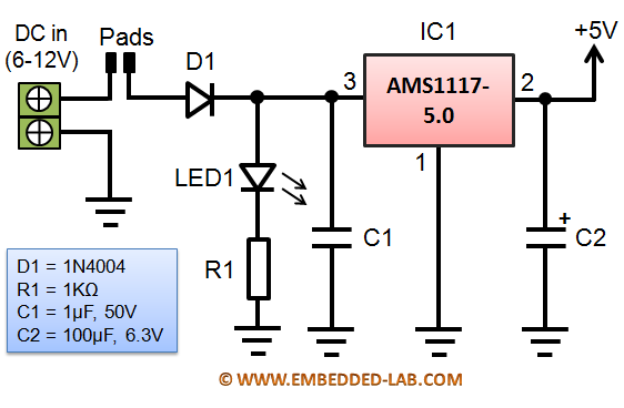
Circuit diagramThe following circuit shows the on-board +5V power supply unit using AMS1117-5.0V regulator IC. The maximum output current of AMS1117 is 800mA, but it is recommended to limit the maximum current to 500mA. The project board can be powered from a 6-12V external power supply connected through a 2-pin terminal block. There is no power ON/OFF switch on-board but users can connect one externally. If no external ON/OFF switch is connected, the pads shown in the figure below must be shorted through soldering.

Power supply circuit on board
The microcontroller circuit (shown below) is straightforward. The GP3/MCLR pin is connected to an external tact switch that can be configured as a reset switch (if MCLR is enabled) or a user input (if MCLR is disabled). All I/O (GP0, GP1, GP2, GP4, and GP5) and power supply (+5V and GND) pins are accessible through headers. A header connector for ICSP using PICKit2/3 is also provided on board.

Microcontroller circuit
Although GP3 is connected to the tact switch input, you can still access it through a plated through hole (PTH) on lower right side of PIC12F IC socket and is labelled as GP3 on PCB (see picture below). There’s a small prototyping area available on the board to add additional components for user projects. If an external ON/OFF switch is to be added into your application, it must be connected to two PTH marked as SW2. Otherwise, the PD1pins must be shorted together for continuous power supply. The picture below shows a closer view of the features on board.

PIC12F project board features
- 2-pin terminal block for DC input (6-12 V DC)
- AMS1117-5.0V regulator
- PIC12F microcontroller on a DIP IC socket
- Tact switch connected to RA3 I/O pin, which is input only. It can be used as reset if MCLR is enabled. It can also be used as an user input if MCLR is disabled.
- Header connector for ICSP programming using chipKIT2/3.
- Headers to access I/O pins and power supply pins (Vcc = +5V).
- Small prototyping area for connecting additional circuit. The regulated +5V power supply for the additional circuit can be derived from the Vcc header pins.
- Plated through holes for connecting an external ON/OFF switch.
The following pictures show assembled PIC12F project board in different configurations. The size of PCB is 1.95″ x 1.95″ (5cm x 5cm).

Assembled PIC12F mini project board with PIC12F1840 plugged in

PIC12F project board with an external ON/OFF switch and powered from a 9V PP3 battery

When no external switch is used, PD1 pins must be shorted
PIC12F mini project board kit on sale
If you are interested you can buy the PIC12F project board as a kit. The picture below shows what you will get in the kit. Note that the kit doesn’t include any microcontroller. You can purchase this on Tindie for $10 plus shipping. Here’s the link: https://tindie.com/shops/rajbex/pic12f-series-microcontrollers-project-board-kit/

Complete PIC12F project board kit

What you will get in the kit
Wondering what you can do with this board? If you search online you will find tons of cool projects done with PIC12F microcontrollers. Here’s a list of few of them.
- A beginner’s data logger with serial interface
- 0-20V digital voltmeter
- Playing a song tune with PIC12F683
- Ultrasonic sound detector
- Metal detector
- PAL video superimposer
- Laser projector
- A super simple IR remote
- Thermometer with Nokia 3310 LCD
- Pong video game
- Mini servo controller
- Temperature sensing mug
- IR light dimmer
Update (October 12, 2012)As I was testing the board I realized that the ground plane on the bottom copper layer has broken apart at a place. I have fixed this manually by soldering the broken parts of the ground plane together (see the picture below). This should not affect the functionality of the board.

Broken ground plane and its fixing
Update (Feb 2, 2013)A revised version of this board was released yesterday with minor improvements. The broken ground plane has been fixed and an additional LED (LED2) is provided on board for user output. The LED can bes connected to the GP5 I/O pin through a 2-pin jumper (J3) on board (see the picture of the new assembled board below).

Revised PIC12F mini development board
You can buy a PIC12F development board kit for $10.99 on Tindie. Buying Link
|
|
Pingback: Mini placa de proyectos para microcontroladores PIC12F | Automatismos Mar del Plata
Pingback: Mini project board for PIC12F series microcontrollers | electronics-projects.info